Table of Contents
Downloading and adapting the (Marlin based) firmware for the ANTCLABS BLTouch
This page will describe using and configuring the firmware from the following repository:
That repository is adapted from the official Marlin repository and is recommended by many people.
If someone needs a more hands on video, showing the process of downloading, adapting and compiling source files, the following video at youtube is recommended.
Although this page is specifically geared towards the following hardware:
- ANYCUBIC I3 MEGA with Trigorilla1.1 board (8-bit, Mega2560 based)
- ANTCLABS BLTouch added
- DRV8825 stepper drivers (Instead of the original A4988 drivers.)
the steps to take in order to create the correct firmware for other hardware and/or other changes are basically very similar.
Adapting and compiling firmware
Many 3d printers use firmware which is created from source files hosted on github. Most of the ready made firmware files on the internet are targeted for original hardware without any modification and cannot be used if something is changed. Modifications are done directly in the source code and thus require small changes to the firmware. It is best to adapt the configuration (for Marlin in the so-called Configuration.h file) and compile yourself.
The process to compile a firmware from sources manually, is not very difficult and can be easily done within the Arduino IDE.
Download and install Arduino IDE
If not done yet, start with downloading and installing Arduino IDE. Follow the official instructions from arduino how to install, given on their webpage.
Get MNieddu91 repository
Clone or download the repository https://github.com/MNieddu91/Marlin-AI3M-BLTouch.git into the directory 01.anycubic_MNieddu91:
git clone https://github.com/MNieddu91/Marlin-AI3M-BLTouch.git 01.anycubic_MNieddu91
Open Marlin.ino
Within Arduino IDE, navigate into the cloned Marlin folder and open Marlin.ino
All files should appear new in separate tabs within Arduino.
Configure Microcontroller and board type
In the IDE, under Tools → Board select Genuino Mega 2560 and ATmega2560
Customization
In the Arduino IDE, go to the Configuration.h file tab (default in: Marlin/Configuration.h)
At the section Stepper Drivers, for optimize timing, change all DRIVER_TYPE into:
DRV8825
(originally this was TMC2208_STANDALONE)
The steps per unit setting also needs to be adjusted to the DRV8825:
#define DEFAULT_AXIS_STEPS_PER_UNIT { 160, 160, 800, 185.20 } // 1/32 Step settings
(originally this was { 80, 80, 400, 92.6 } // 1/16 Step settings)
Change the direction of the stepper (// @section machine) in the following:
#define INVERT_X_DIR true // set to true for DRV8825
#define INVERT_Y_DIR false // set to false for DRV8825
#define INVERT_Z_DIR false // set to false for DRV8825
Change the extruder direction (// @section extruder) in the following:
#define INVERT_E0_DIR false // set to false for DRV8825
#define INVERT_E1_DIR false // set to false for DRV8825
Flashing firmware
Once compiled, the firmware can be flashed directly from within the Arduino IDE.

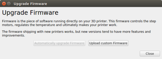
Alternatively, the firmware can be compiled in Arduino into a hex file (Using Sketch → Export compiled binary) and then be flashed with Ultimaker CURA using the Marlin.ino.hex file in your Marlin directory. For this, please follow the screenshots below showing the process to upload the new firmware to the anycubic i3 MEGA. When done, restart the printer.
Test and calibration procedure
This test and calibration procedure is based on the github description of davidramiro.
Typically these are:
- Calibration instructions here: https://github.com/davidramiro/Marlin-AI3M/wiki/Calibration/
- BLTouch calibration: https://github.com/MNieddu91/Marlin-AI3M-BLTouch/wiki
In order to perform a test and calibration procedure, it is necessary to send custom commands ( Like "M503") directly to the printer. For this you would normally use a serial console application. There are some issues however with such applications as described in footnote 1).
The easiest solution to send a command is the open source application Pronterface 2) which runs on multiple platforms. Before sending a command, make sure to configure a baudrate of 250000bps and press connect.
If someone prefers to use the serial console built in with the arduino IDE, then proceed as described here.
Extruder intake
After following the extruder intake calibration procedure it was observed that instead of 100mm the intake was only 95mm, So this resulted into the following DEFAULT_AXIS_STEPS_PER_UNIT in Configuration.h:
//Old value: #define DEFAULT_AXIS_STEPS_PER_UNIT   { 160, 160, 800, 185.20 }
#define DEFAULT_AXIS_STEPS_PER_UNIT   { 160, 160, 800, 194.95 }
Probe offset
From the BLTouch calibration description, the following changes in Configuration.h where done:
//#define Y_PROBE_OFFSET_FROM_EXTRUDER -23  // Y offset: -front +behind [the nozzle]
#define Y_PROBE_OFFSET_FROM_EXTRUDER -24  // Y offset: -front +behind [the nozzle]
Because the Ultrabase plate is held onto place with Kapton sticky tape, the boundaries need to be reduced where the probe can reach. This prevents that probing is done onto the sticky tape.
  // Set the boundaries for probing (where the probe can reach).
  //  #define LEFT_PROBE_BED_POSITION 10
  //  #define RIGHT_PROBE_BED_POSITION 190
  //  #define FRONT_PROBE_BED_POSITION 10
  //  #define BACK_PROBE_BED_POSITION 202
  #define LEFT_PROBE_BED_POSITION 24
  #define RIGHT_PROBE_BED_POSITION 190
  #define FRONT_PROBE_BED_POSITION 40
  #define BACK_PROBE_BED_POSITION 190
Although the board is the newer Trigorilla 1.1 version, the BLTouch is connected to the original pins D2/D11. Therefore it is not required to change the TRIGORILLA_VERSION setting in the source file. This is perfectly explained on the following page.
After the Z_PROBE_OFFSET_FROM_EXTRUDER was determined, the following was modifed:
//#define Z_PROBE_OFFSET_FROM_EXTRUDER 0   // Z offset: -below +above  [the nozzle]
#define Z_PROBE_OFFSET_FROM_EXTRUDER -0.4   // Z offset: -below +above  [the nozzle]
And recompiled and flashed onto the controller. Then finally two commands where issued to make these settings effective:
M502 (Load setting hardcoded in firmware)
M500 (save settings in EEPROM)
This will as well solve the “EEPROM version mismatch” warning.
To print a concise report of all current settings (in SRAM), issue the following command:
M503 (print a concise report of all current settings)


