Table of Contents
Measuring heat-pipe quality
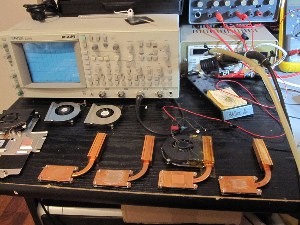
This page describes test procedures, measurements and results from comparing heat transfer capabilities between a certain type of heat-pipes used in certain Compaq laptops.
Test method
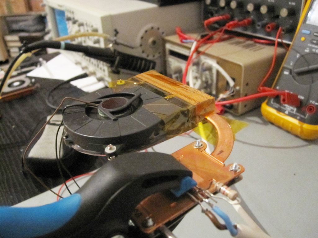
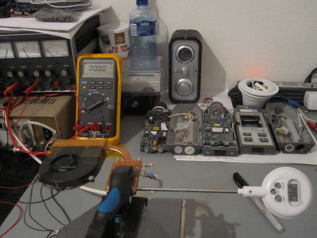
- As heat source a TIP42C PNP-transistor was used with a 56Ω resistor between the basis and the collector. During testing the maximum emitter-base voltage was measured and well below the maximum of 5v.
During heat dissipation, the supplied voltage between the emitter and collector was 6v, while the current was about 3A. Due to the temperature increase, the base current would vary and as such the collector current accordingly. Therefore the power consumption is an estimation and according to observations found to be about 18.5w ± 0.5w. - The fan which Compaq used in the laptop was used and ran at maximum speed, at 5v. With sticky tape all air was forced to flow through the narrow radiator channel.
- The ambient temperature was 22.1°C.
- After powering up fan and transistor, every 5 seconds a temperature reading was recorded from the temperature sensor. After 120 seconds the temperature would not vary very much and instead of recording every 5 seconds, 4 minutes had been waited and the final temperature had been read. At this moment all of the heat-pipes (Except #0) were in a thermal equilibrium.
Results
Conclusion
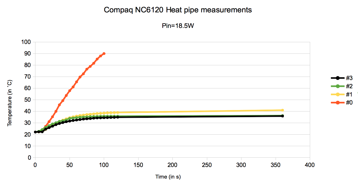
- Heat-pipe #0 is clearly broken. Because energy was not released into the air via the cooling fins, the temperature rose at the copper area where the transistor was mounted. This can be seen in the graph. Further measurements at this heat-pipe had to be stopped to prevent damage to the transistor.
- The largest differences were to be found between heat-pipe 1 and 3. At thermal equilibrium the temperature difference was about 4.5 °C.
- Heat-pipe #3 performs the best. At a room temperature of 22.1 °C, the final temperature when no further rise or fall can be detected is 35.9 °C. The dissipated power had been set to 18.5W.


