Table of Contents
Philips PE1542 Power Supply repair
The Philips PE 1542 is a power supply which consists of three adjustable outputs, linear regulating, non-switching type. For sensitive measurements where signal spectrum measurements are required, switching type power supplies are less suitable, because they generate small amounts of (harmonic) signal noise themselves. Linear regulators are therefore most suitable for such applications. The power supply is based around three modules with each having a traditional ua723c regulator IC. The specifications of the power supply are:
- 2x 0-20v, 0-1A
- 1x 0-7v, 0-3A
- Each of the three channels has a traditional galvanometer-based display, which shows either voltage or current. A switch determines which one of the two is displayed.
Noise decoupling
The mains transformer induced some annoying mechanical vibration which was too well hearable. Internally the transformer was mounted directly on the back frame. The solution was to add small rubber vibration absorber between the transformer and the back frame. The result was immediately noticeable. The power supply became completely silent after this.
 |
| Philips PE 1542 transformer decoupling solution |
|---|
Galvanometer issue
Recently, one of the channels of the power supply spontaneously stopped working. When wiggling slightly with the knobs, the reading would come back, but this did not last very long. My initial thoughts were this would be related to a bad solder somewhere or bad potentiometer. After opening the device and inspecting the circuit board I did not see something unusual. So I started measuring. The ua723c had correct power supply, produced a stable reference voltage as well. By chance I noticed, when I pressed somewhere on the circuit board, the reading would come back. After this I noticed that the output terminals were also fine and giving a stabilized voltage, regardless of the reading of the galvanometer. So then I discovered something was wrong with the galvanometer and not something else and focussed on this part. I looked on the circuit board and followed the copper traces which were going to the galvanometer and measured voltage levels. That looked fine, however a very strange thing I noticed was that one of the concerning threads which came out of the galvanometer and was fixed onto the circuit board with the nuts, one above and one below, did not measured the correct voltage. Something really weird, because the nut on the bottom made contact with the copper correctly and was around the same thread as the top nut. Nevertheless it showed a different voltage. Please see the images below to get an idea. To solve this properly, the best would be probably to open the galvanometer and verify how the thread is internally connected. Maybe it would also suffice to rotate the nut on the bottom slightly more towards the circuit board to make sure the thread is really touching the nut. As the first solution would required quite a lot of further dismantling and the second solution would still be a possible cause for errors in the future, I decided to create an additional connection on the top. This works fine. Maybe a tip for anyone experiencing a similar behavior.
 |  |  |
| Philips PE 1542 circuit board | Galvanometer bottom nut | Galvanometer bypass from top thread |
|---|
Service/Maintenance
All 6 potentiometers to set voltage/current and the 3 voltage/current switches on the front suffer from ageing. After searching, the following replacement parts were ordered:
- 3x Switch DPDT, ON-ON, C&K Components (Farnell: 143-7699 / Manufacturer Art. Nr. 1201M2S3CQE2)
- 6X POTENTIOMETER, LINEAR, 2K2, 3W, 10% PE30L0FR222KAB By VISHAY (Farnell: 1141632)
Unfortunately, none of these parts are a direct replacement. Therefore some mechanical work is required to make these parts fit:
- Mount the 6 potentiometers on an aluminium L-profile, Mount the whole assembly on the front panel with two spacers.
- Mount each switch behind an existing switch, by removing the original contacts. Then cut a square hole at the back of the original plastic handle. By shortening the handle of the new switch, at will fit into the back of the old handle. Use a small test circuit board or similar and some threaded rod (Which I soldered to the metal casing of the original switch) and screws to mount the new switch.
- On the main PCB, increase the 6 holes for the potentiometers to a diameter of 12mm. The new potentiometers are too short and must be soldered using additional wires, as can be seen on the last picture below.
Below some pictures of the Philips PE 1542:
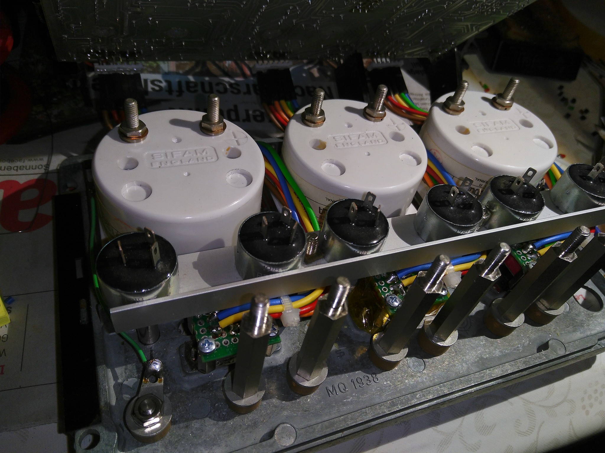 | 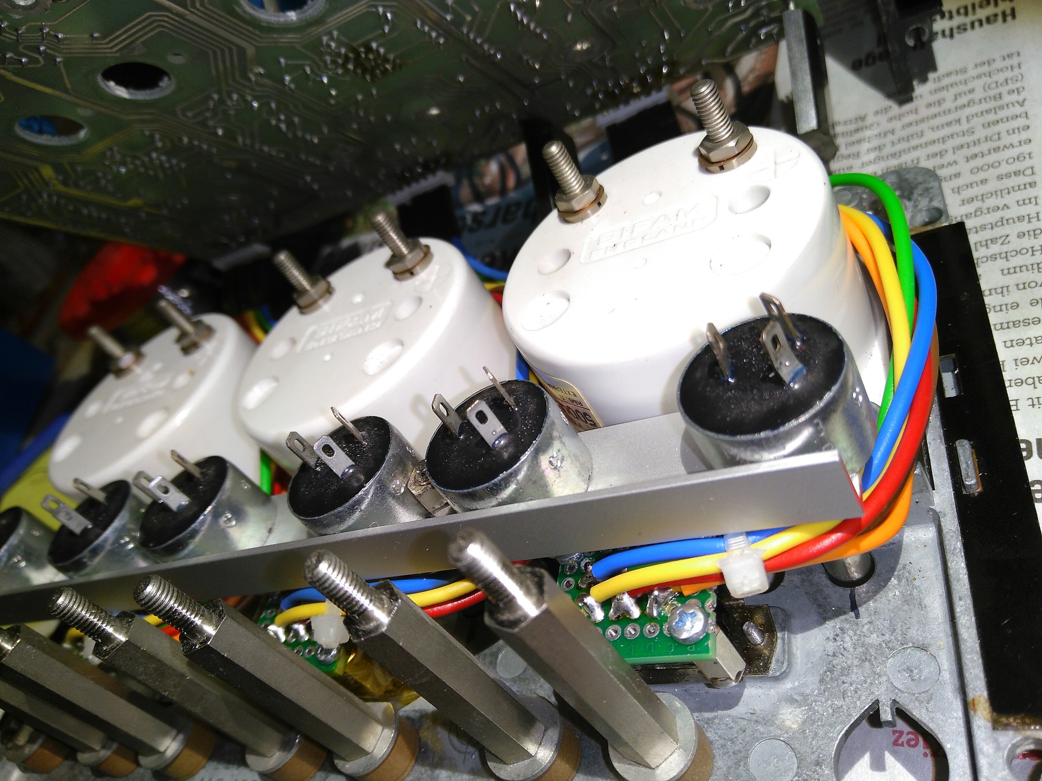 | 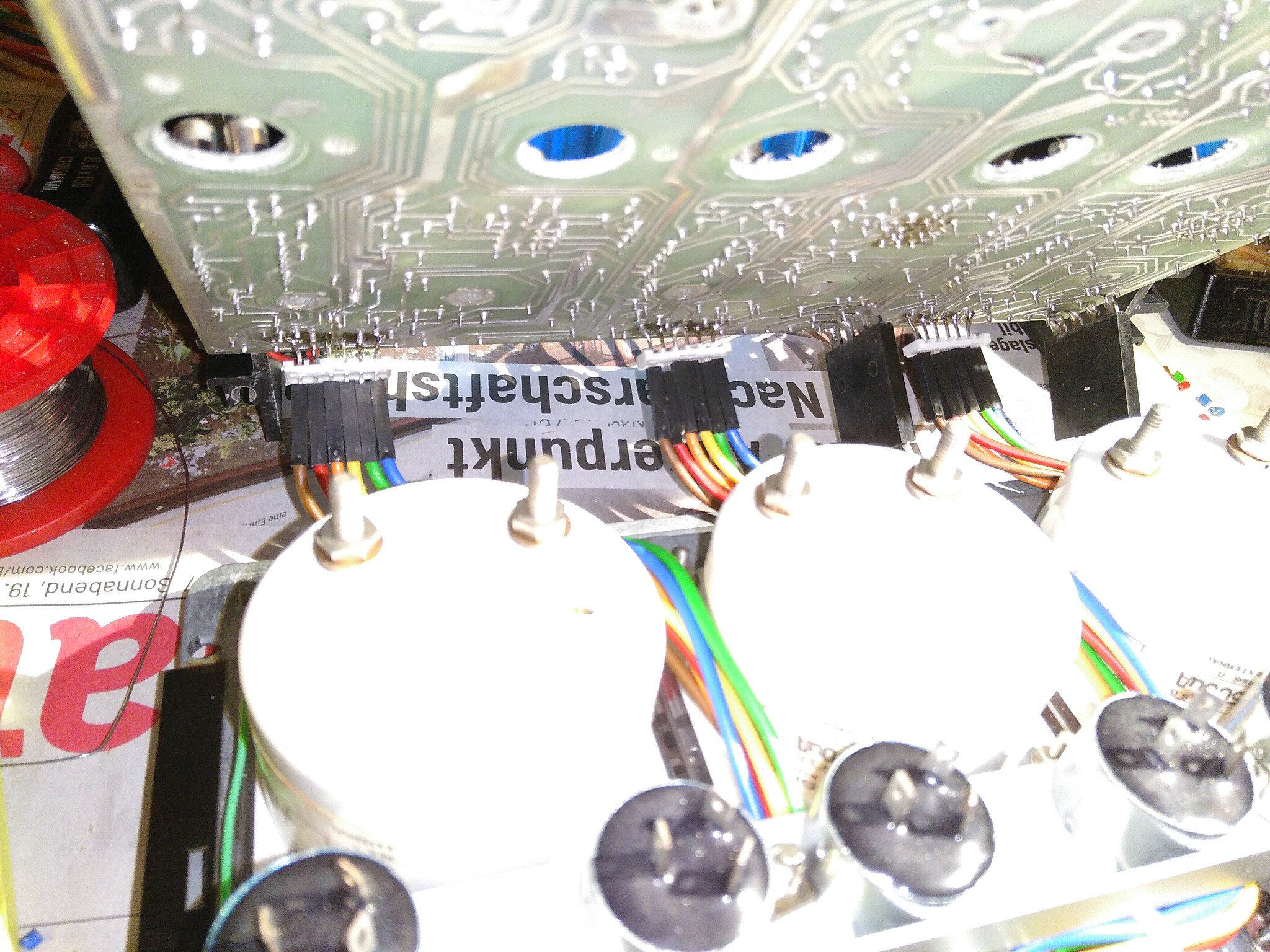 |
| back - I | back - II | Dupont connectors for connecting switches to main board |
|---|
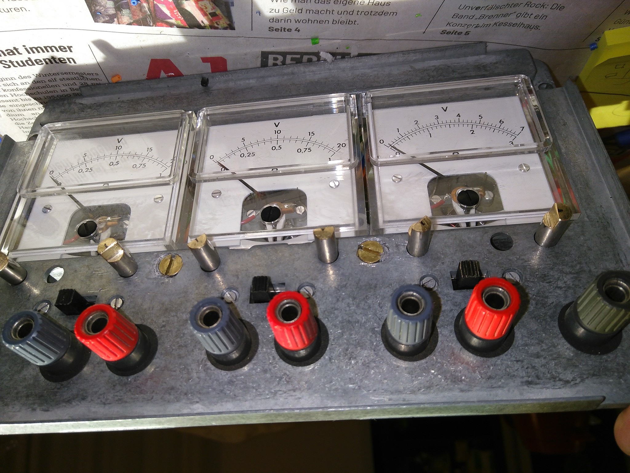 | 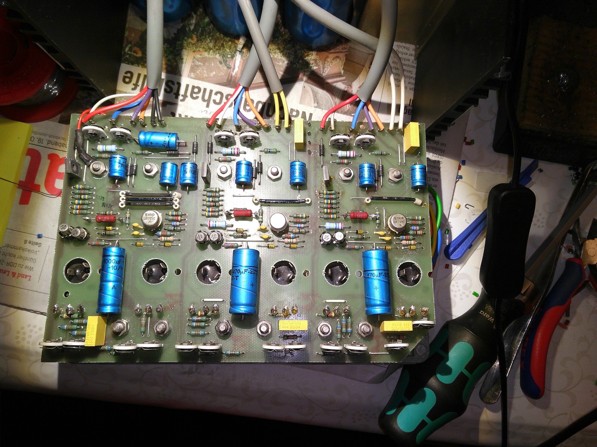 |  |
| front | PCB - I | PCB - II |
|---|