This is an old revision of the document!
Table of Contents
B&O Beogram 8000 turntable repair
Repair of a B&O Beogram 8000 turntable with following issue:
- sudden speed increase, without any apparent reason. Originally about every 20 minutes, for a duration of 5 seconds.
- Schematic diagram can be obtained free of charge here (Free for personal use.)
After measuring with an oscilloscope on some meaningful points in the circuit, there were no anomalies found. Signals looked as expected. Since the speed control circuit as a whole is in a closed loop, the cause could be anywhere as well within the loop. A better way to measure therefore was to place measuring probes before and after several functional blocks in the closed loop and see for each block how it behaves when speed increases suddenly. For this a Saleae capture device (Logic Pro 8) was used. With that the reason for the speed error was found:
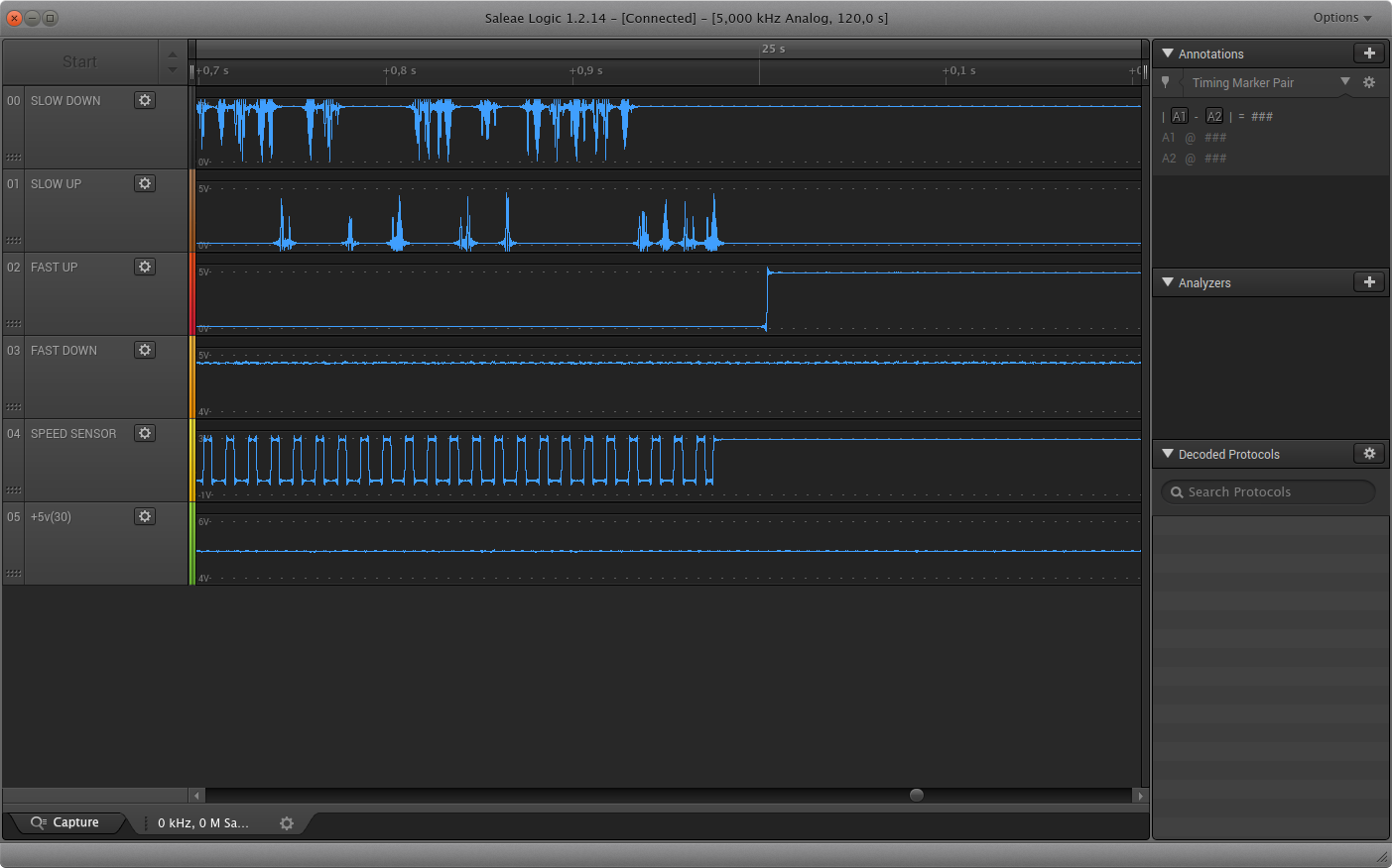 |
| Speed sensor stops sensing → FAST UP switches on |
As can be seen from the image, the speed sensors stops working, causing the FAST-UP to be active and as such the speed increases. The signal for the speed sensor was measured at the B&O microcontroller. In normal cases the speed control only uses the SLOW UP and SLOW DOWN controls of the microcontroller:
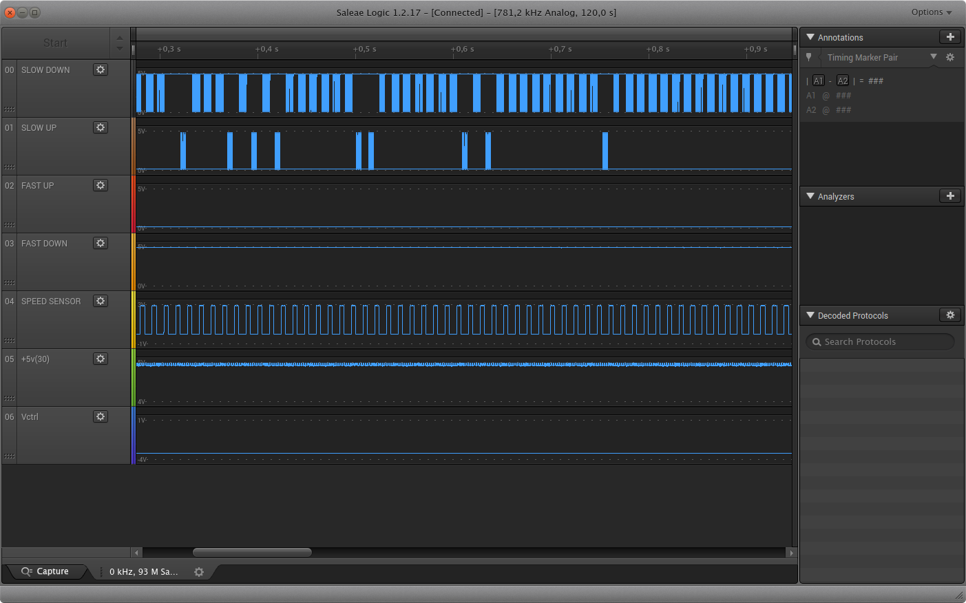 | 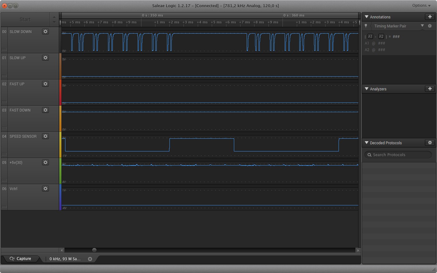 |
| Normal operation: Only SLOW UP/DOWN | Zooming in |
So to find the cause for this, the circuit which handles the speed sensor was analyzed:
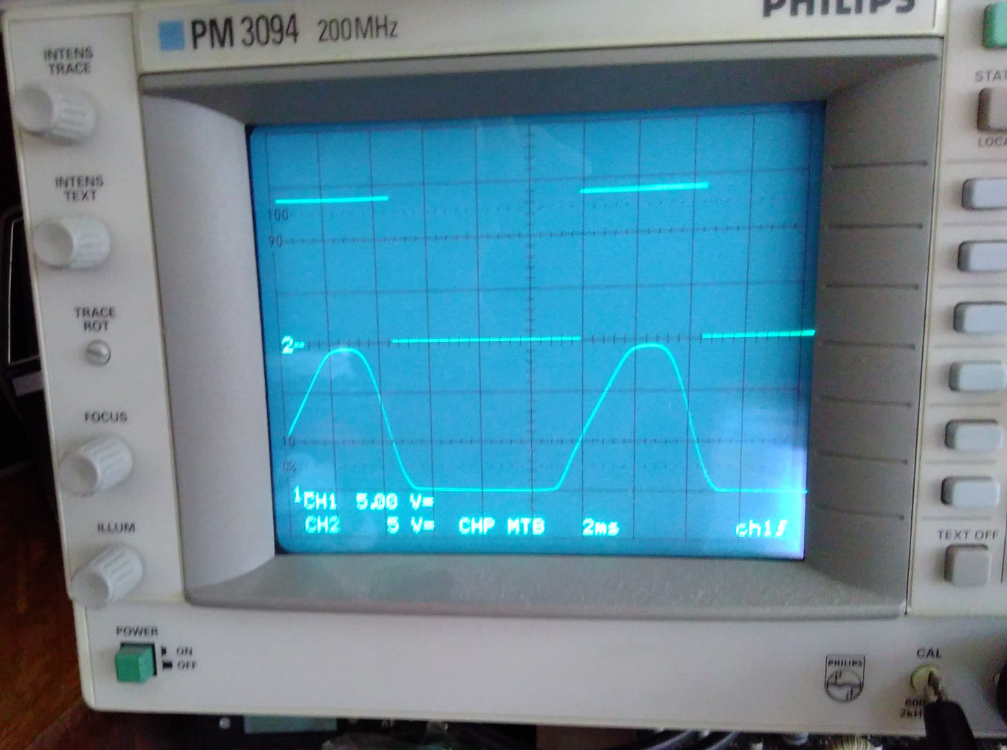 |
| CH1: OPE1 phototransistor, CH2: Output of opamp/schmitt trigger |
The B&O diagram from above is a bit different then what this turntable has: Phototransistor OPE2 is pulled up to 15v with resistor R47 (22k) and fed via resistor R48 (100k) to opamp IC1, which is configured as a 5v comparator (with a feedback of R49 (1M0). The output of the comparator is fed via a voltage divider (consisting of resistor R50 and R51) into the microcontroller. This is also different than what is designed in the circuit diagram from above. Maybe the 4013 schmitt-trigger was added in a later revision as a modulator for the speed signal.
With the limited triggering possibilities of the oscilloscope, measuring both signals for a long duration while staring at it and wait until one could see where the root cause was, was quite hard. Also, while investigating this, the cause did not appear a single time while observing. Still without repairing anything specific, it was difficult to understand that defects would be fixed somehow spontaneously. Due to this long duration, the Saleae analogue capturing device was not suitable either, because of the limited sampling time. Then, to find the root-cause (Or at least prove that the cause was not anymore present), a simple but effective Arduino Nano microcontroller as watchdog was taken. With some software it was able to guard both signals and indicate if one or both signals would fail and if speed was deviating from 33 1/3rpm.
To reduce the influence of the Arduino measurement system, two opamps as voltage-followers were taken, fed with 20v to allow some margin above the 15v level to be measured:
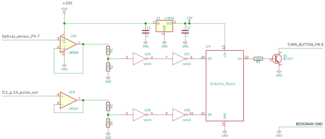
Both input signals, Optical_sensor_P4.7 and IC1_p.14_pulse_out, are between 0v and 15v. The LM324 is here practical for interfacing, since for a single power supply, Vout can go to ground if sensing is near ground and this can then be easily converted to logic levels for the Arduino Nano. For this two cd4049 hex buffers in series were taken, only to create logic voltage levels with sharper edges.
As the turntable always stops turning after about 30 minutes, transistor Q1 was selected to 'hit' the TURN-button periodically.
A 5v regulator was chosen to regulate 20v down to 5v for the Arduino Nano, if the Nano was not connected via USB to a computer. The 20v made it easy that only one power supply was required.
Monitoring speed with software
The software which monitors speed and pulses is based on two cascaded interrupts. If pulses would cause an interrupt in a different order than expected, software recognizes this. Also, if pulses do not appear within the expected time (12ms per pulse), it is also recognized.
/**
 * Software to measure and monitor speed of 33 1/3 rpm turntable
 * from B&O, Beogram 8000.
 *
 * count unit:
 *    12 seconds == 1000 pulses
 *   150 pulses == 1 round
 *    60 seconds == 33.3333 rounds
 *
 * So per 12 seconds we have: 6.666666 rpm.
 *  Each 6.66666 rpm takes about 12000 ms, or:
 *  6.66666 / 12000 per ms.
 *  If t is the time in ms for 1000 pulses, then the
 *  number of rounds is: 12000 * 6.66666 / t
 *  To show the rpm, multiply the result with 60/12 = 5,
 *  which result in an rpm for 1000 pulses as:
 *  t * 33.33333 * (12000/t)
 *
 * Author: Marc Nijdam
 * License: MIT
 * Date: 12.01.2018
 */

/* constants */
const static unsigned char pulse_per_round = 150;
const static unsigned char INFO = 0;
const static unsigned char SPD = 1;
const static unsigned char SENS = 2;
const static unsigned char tolerance = 50; /* tolerance in us for measuring speed */
const static unsigned int MAX_COUNTS = 1000;

/* pins */
const static unsigned char optoPin = 2; /* corresponds with optoIRQ 0 */
const static unsigned char optoIRQ = 0;
const static unsigned char pulsePin = 3; /* corresponds with optoIRQ 1 */
const static unsigned char pulseIRQ = 1;
const static unsigned char out1_pin = 11;
const static unsigned char out2_pin = 12;
const static unsigned char turn_on_pin = 4;

/* variables */
static unsigned int total_wrong_speed = 0;
static unsigned int count_sensor_problem = 0;
volatile unsigned int count_series = 0;
volatile unsigned int count_opto = 0;
volatile unsigned int count_pulse = 0;

volatile unsigned char opto_sync_ok = 0;
volatile unsigned char sync_follow = 0;
volatile unsigned char data_ready = 0;

volatile unsigned long t_opto = 0;
volatile unsigned long t_pulse = 0;
volatile unsigned long t_round = 0;
volatile unsigned long t_diff = 0;
volatile unsigned long t_futurepulse = 0;
static unsigned long t_start = 0;
static unsigned long t_seconds = 0;
static unsigned long t_future = 0;
static unsigned long t_turnbutton_release = 0;
static unsigned long t_now = 0;

/* function prototypes */
void sync_opto(void);
void do_init(void);
void disable_opto_pulse_IRQs(void);
void enable_opto_pulse_IRQs(void);
void press_turn(void);
void irq_opto(void);
void irq_pulse(void);
void test_init(void);
void output_txt(unsigned char type, char * txt);

/* start */
void setup() {
  do_init();
  Serial.begin(9600);
  test_init();

  /* press turn button shortly */
  press_turn();
  delay(5000); /* wait 5 seconds to stabilize */
  /* synchronize with opto falling low*/
  interrupts();
  disable_opto_pulse_IRQs();
  sync_opto();
  enable_opto_pulse_IRQs();
  t_start = millis();
  t_round = t_start;
}

void loop() {

  /* wait one non-blocking second... */
  do {
    t_now = millis();
    /* handle release turn button if t_turnbutton_release != 0 */
    if (t_turnbutton_release && t_now > t_turnbutton_release) {
      t_turnbutton_release = 0;
      digitalWrite(turn_on_pin, 0);
    }
  } while (millis() < t_future && !data_ready);
  t_future = millis() + 1000;

  /* ... and quickly check speed and sensor */
  disable_opto_pulse_IRQs();
  t_seconds = (t_now - t_start) / 1000; /* measure time max 50 days */
  if (data_ready) { /* 12 seconds */

    /* check if speed correct? */
    if ((t_diff < 12000 - tolerance || t_diff > 12000 + tolerance)) {
      total_wrong_speed++;
      output_txt(SPD,"Speed bad");
    } else if (count_series <= count_opto + 1 && count_series <= count_pulse) {
      output_txt(INFO,"");
    } else {
      output_txt(SENS,"Sensor(s) bad");
    }
    opto_sync_ok = 0;
    data_ready = 0;
    sync_opto();
    press_turn();
    t_now = millis();
    t_round = t_now;
     /* check if sensor is not detecting pulses */
  } else {
    if (t_now > t_round && t_now - t_round > (12000 + 3 * tolerance)) {
      count_sensor_problem++;
      output_txt(SENS, "Sensor(s) dead?");
      opto_sync_ok = 0;
      data_ready = 0;
      sync_opto();
      press_turn();
      t_round = t_now;
    }
  }
  enable_opto_pulse_IRQs();

}

/* make sure that function finishes with positive edge */
/* typically the duty cycle of the signal is 2/11 (high/low) */
void sync_opto(void) {
  unsigned long t1;
  unsigned long t2;
  unsigned long t;

  /* 1. wait for start signal */
  t = millis();
  do {} while (!digitalRead(optoPin) && millis() - t < 14);
  do {
    t = millis();
    delayMicroseconds(100);
    do {} while (digitalRead(optoPin) && millis() - t < 14);
    t1 = millis() - t;
    t = millis();
    delayMicroseconds(100);
    do {} while (!digitalRead(optoPin) && millis() - t < 14);
    t2 = millis() - t;
  } while (t1 + t2 < 11);
  if (t1 > t2) {
    t = millis();
    delayMicroseconds(100);
    do {} while (!digitalRead(optoPin) && millis() - t < 14);
  }
  delayMicroseconds(100);
}

void do_init(void) {
  pinMode(pulsePin, INPUT);
  pinMode(optoPin, INPUT);
  pinMode(turn_on_pin, OUTPUT);
  digitalWrite(turn_on_pin, 0);
}

void disable_opto_pulse_IRQs(void) {
  noInterrupts();
  detachInterrupt(optoIRQ);
  detachInterrupt(pulseIRQ);
  interrupts();
}

void enable_opto_pulse_IRQs(void) {
  noInterrupts();
  attachInterrupt(optoIRQ, irq_opto, FALLING);
  attachInterrupt(pulseIRQ, irq_pulse, FALLING);
  interrupts();
}


void press_turn(void) {
  digitalWrite(turn_on_pin, 1);
  t_turnbutton_release = millis() + 1000;
}

void irq_opto(void) {
  if (digitalRead(optoPin)) {
    return;
  }
  if (!opto_sync_ok) { /* make sure trigger is if signal was falling */
    t_opto = millis();
    t_round = t_opto;
    count_opto = 0;
    count_pulse = 0;
    count_series = 0;
    opto_sync_ok = 1;
  } else {
    if (millis() - t_opto >= 11) {
      t_opto = millis();
      count_opto++;
      sync_follow = 1;
      digitalWrite(out1_pin, !digitalRead(out1_pin));
    }
  }
}

void irq_pulse(void) {
  if (digitalRead(pulsePin) || !opto_sync_ok) {
    return;
  }

  t_pulse = millis(); /* debouncing */
  if (t_pulse > t_futurepulse) {
    t_futurepulse = t_pulse + 10;
    digitalWrite(out2_pin, !digitalRead(out2_pin));
    if (sync_follow) {
      sync_follow = 0;
      if (count_series == MAX_COUNTS - 1) {
        t_diff = millis() - t_round; /* total time for 1000 pulses */
        data_ready = 1; /* indicate to loop() to process data */
        return;
      } else {
        count_series++;
      }
    }
    count_pulse++;
  }
}

void test_init(void) {
  pinMode(out1_pin, OUTPUT);
  pinMode(out2_pin, OUTPUT);
  digitalWrite(out1_pin, 0);
  digitalWrite(out2_pin, 0);
}

void output_txt(unsigned char type, char * txt) {
  float rpm = (33.33333 * (12000.0 - 12.0)) / t_diff; /* omit last round */
  unsigned int h = t_seconds/3600;
  unsigned int m = (t_seconds/60) % 60;
  unsigned int s = t_seconds % 60;
  char buf[16];
  if (!type == INFO) {
      Serial.print(">");
  }
  sprintf(buf, "%02u:%02u:%02u", h, m, s);
  Serial.print(buf);
  Serial.print(", ");
  Serial.print(rpm, 2);
  Serial.print("rpm, SENSOR/AMP:");
  Serial.print(count_opto);
  Serial.print("/");
  Serial.print(count_pulse);
  Serial.print(", (#");
  Serial.print(total_wrong_speed); // in 12 seconds interval
  Serial.print("/#");
  Serial.print(count_sensor_problem); // sensor fails
  switch (type) {
    case SPD:
    case SENS:
      Serial.print(") - ");
      Serial.println(txt);
      break;
    default:
      Serial.println(")");
      break;
  }
}
Root cause
After testing for several days, the error did not come back at all. Further analysis found that the most likely cause for the failing sensor was wrong alignment of the optical sensor unit (8005067). The sensor was too far in and with releasing the adjustment screw, it was possible to move it. Most likely, by touching the optical sensor unit, it had been shifted in the good direction. Without knowing that, it solved the problem!
References and further information
- See about interrupts: http://www.gammon.com.au/interrupts
- Variables to be declared volatile
Page Tools
