Table of Contents
Omni200
The omni200 printer is manufacturer by OEM Goofoo, and sold by the polish company Omni3d. The original OEM product is sold under several names:
- Renkforce Pro 6 3D Printer → https://www.conrad.de/de/p/renkforce-pro-6-3d-drucker-2356116.html
- Renkforce Pro 3 3D Printer → https://www.conrad.de/de/p/renkforce-pro3-3d-drucker-inkl-filament-2159185.html
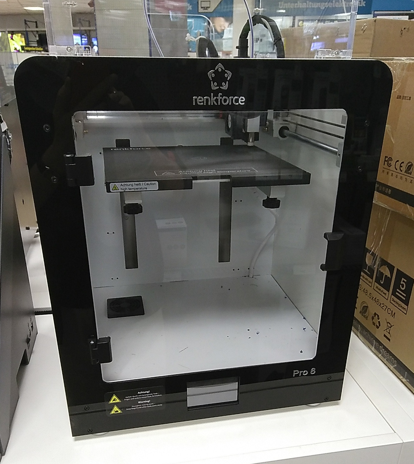 |  | 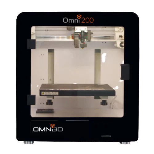 |
| Renkforce Pro6 | Goofoo Mido | Omni3d Omni200 |
The printer has an enclosure and allows for printing with materials which require this, like ABS. The construction of the printer is sturdy and allows accurate and recurring printing results. The controller is an STM32 - Chitu based. Operation of the printer is due to trinamic stepper drivers very silent.
Between these products it is likely that also controllers (Chitu-based) are slightly different.
Some internet forums describing this product can be seen here:
Product descriptions can be seen here:
Omni200 features
Controller specifications
- Chitu FX446 Controller board
- Processor: STM32F446
- Pinout: chitu_fx
Printhead modification
The omni200 printhead is connected via a strand of wrapped cables which are attached to a holder at the beginning and at the end. The wrapping consists of some kind of fabric sticky tape and does not really provide a means to control bending radius. To improve this, the best would be to swap the cables for an FFC-cable, which on it its own provides enough flexibility and sturdiness to carry its own weight and still bend evenly under all circumstances.
Another major advantage of using an FFC-cable is that it offers a few more wires, which can be used for future extensions, like a laser-based proximity sensor (see here for a description and pictures, or an additional filament runout sensor.
The main modification consists of two new circuit boards, one to be attached to the rear of the inner housing and one to be mounted on the printhead itself. Since the circuit board at the printhead kept the same connectors, crimping of cables was not required. At the other end of the FFC-cable, the circuit board which was mounted at the back plate, required the cables from the controller board to be shortened and crimped.
| Design files | ||
|---|---|---|
| FILE | TYPE | DESCRIPTION |
| KiCAD_Goofoo_flexcable_dist.zip (KiCAD 5.0) | KiCAD project | Schematic drawing, circuit board design, BOM, 3D-files |
| Goofoo_fan_mount_cnc.zip | svg, dxf | FAN mount dxf file for CNC machine |
| Goofoo_3D_printer_parts.FCStd (FreeCAD) | FCStd | 3D-printable cover and guide for printhead |
| Goofoo_rear_cover.FCStd (FreeCAD) | FCStd | 3D-printable cover for rear circuit board |
The main changes where done in roughly four steps:
- To let the FFC-cable keep its maximum bending radius it was necessary to mill away the top of the right guide on the X-axis. Another advantage of this was that it reduced some weight.
- A cutout and 3 holes were needed at the back plate for mounting the (stationary) circuit board.
- An aluminum bracket was engraved to keep the right fan into place. The original bracket was much larger and made out of iron. The aluminum reduced the weight as well further.
- Holes at the circuit board at the head carriage were located at the same location where the original holes where, so the mounting of this board was straightforward.
Some pictures of the design:
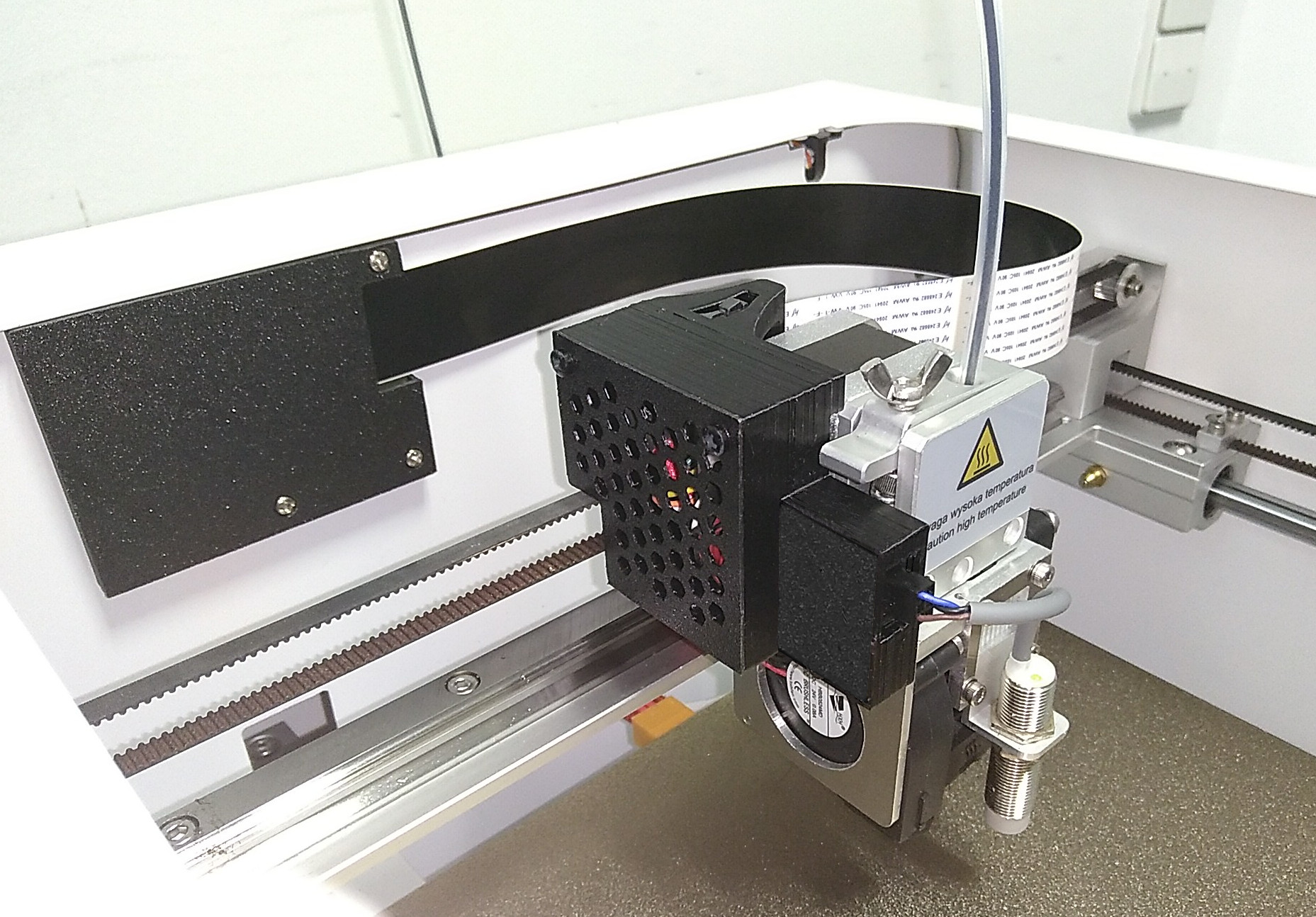
 |  |
| Dismantling X-axis, removing right guide | engraving top |
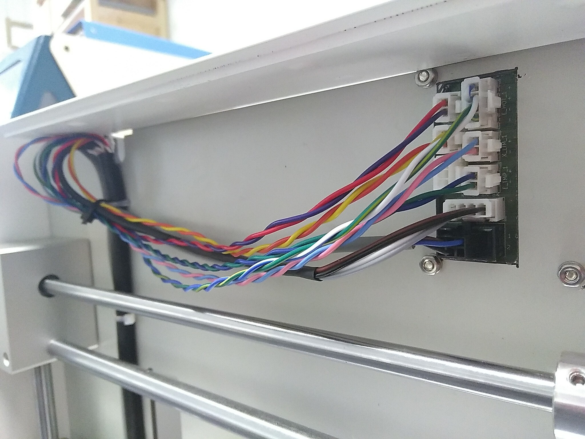 |  |
| Connecting wires at the back | Overview |
A short video of the printer and cable in action can be seen here:
After about three months of use the FFC-cable solution is stable and no issues have been seen. To protect the circuit boards and the printer, small enclosures for the PCBs were designed and printed, which looks like:
 |
| enclosures for the two circuit boards as well as a guide for the FFC-cable |
Heated bed - Build plate
The omni200 build plate consists of an aluminum plate with a flexible circuit board glued to the bottom. On the top there is a magnetic layer which holds an iron plate (about 2mm thick) into place. Then on the other side of the iron plate you can find the so-called Magnetic build plate for 3D printers.
After some usage with printing ABS, the iron plate may get stuck, like glued, to the lower magnetic layer and as such cannot be separated from each other anymore. The problem with this is that upon heating, the bottom aluminum plate expands differently than the iron plate and as such warping to some degree will happen.
A solution for this, is to -as long as it is still possible- remove the iron and build plate from the lower magnetic layer and use a powder coated PEI plate instead. Information about the plate:
- Supplier: https://www.cr-3d.de
- Art. No. 3D-SWAP-PWPEI-250250
- Description: Powder Coated PEI 250 x 250 (VORON), Federstahlplatte inkl. doppelseitiger Powder Coated PEI Beschichtung,
- Thickness: 0.5mm
- Cost: 41.93 Euro
See also: https://www.vorondesign.com/sourcing_guide
According to the company which produces the Omni200, there are some safety concerns with the connector at the heated bed, which seems to be not rated for the current which it consumes and may melt. It is recommended to replace this with the following:
- 1x MOLEX 39012080 - Mini-Fit JR - 2×4 pin - Connector
- 1x MOLEX 39301080 - Mini-Fit JR - 2×4-pin - Angular PCB mount header
This solution should be an in-place replacement and does not require any soldering of wires. Only the header needs to be soldered to the heater of the build plate. The new connector will allow a current of 9A per pin. Combining 3 pins for heating on positive side and similar on negative side, should be enough, The two remaining connections can then be used for the thermistor.
Omni200 Cura configuration
Issues and solutions
Over-extruding at first layer
Try keeping Cura setting “Initial Layer Flow” to 100%, but adjust the Z-offset for the first layer. Calibrate the E-step setting for the extrusion stepper motor. In my case, with a factory default setting the “G1 F100 E100” command extruded only 85mm instead of 100mm filament. Only after a correction (with sending “M8011 0.01373” and M8500 to save settings), the extrusion was exactly 100mm. Also note that after much empirical testing, the first layer distance to the build plate after homing had to be set to 0.07mm, using the supplied spacer gauge: filament sticks well to the build plate and the first layer revealed evenly strokes of filament.
Uneven layers on one or more axis
 |
| stepper skipping steps |
Increase the electrical current of the concerning stepper motor by turning the related potentiometer (marked on the circuit board as R4_X, R4_Y, R4_Z) slightly counter-clockwise.
Klipper installation
- Moonraker: (Python 3 based web server that exposes APIs with which client applications may use to interact with the 3D printing firmware Klipper
- All in one: https://docs.mainsail.xyz/
Hacking the Chitu STM32F446-based board
With the purpose to install klipper on the board, information is collected below.
One open task is to reverse engineer the Chitu board far enough to know which GPIO is connected to which driver/mosfet/interface etc.
Details about how the STM32 controller is interfaced to the peripheral can be found here.
Prerequisites
Building st-link software
To communicate with the ST-Link V2 hardware we will use the open source version of the STMicroelectronics STLINK Tools. Since this depends on libusb, we need to install this first:
sudo apt-get install libusb-1.0-0-dev
Then proceed accordingly:
git clone https://github.com/texane/stlink.git
cd stlink
make release
sudo make install

# copy the resulted files to the system
cd build/Release/bin
sudo cp st-* /usr/local/bin
cd ../lib
sudo cp *.so* /usr/local/lib

# copy udev rules to /etc/udev/rules.d
sudo cp ../../../config/udev/rules.d/49-stlinkv* /etc/udev/rules.d/

# Verify that there is no line with " libstlink.so.1 => not found" with the following command:
ldd /usr/local/bin/st-util
References and further information:
Using STLink V2
Generally to read or write to an STM32 with STLink, the pinout and connection of would be:
 |
| ST-LINK/V2, 20-pin JTAG connection pin numbering |
With the following relevant pins (LQFP144 footprint):
| STLink V2 pin | STLink V2 function | STM32F446 pin | STM32F446 function | Description | ||
|---|---|---|---|---|---|---|
| 1 + 2 | VAPP | * | MCU VDD | Target VCC, optional | ||
| 9 | TCK_SWCLK | 109, PA14 | CLK / SWCLK / JTCK-SWCLK | Serial Wire Clock | ||
| 12, 18, 20 | GND | * | GND | System ground connection | ||
| 7 | TMS_SWDIO | 105, PA13 | DIO / SWDIO / JTMS-SWDIO | Serial Wire Data In and Out | ||
| 15 | NRST | 25 | NRST | Reset Signal, optional. Helpful if the SWD interface was disabled via software. Alternatively BOOT0 set to high would activate the bootloader and keep SWD enabled | ||
| 13 | TDO_SWO | 133, PB3 | SWO | Serial wire output, optional |
For the Chitu FX446 Controller board, header J17 carries all the relevant signals to connect the STLINK V21):
| Chitu FX446 J17 | Marking | STLINK V2 pin | STLINK V2 signal | Description |
|---|---|---|---|---|
| 1 | VCC | 2 | VAPP | Target VCC |
| 2 | SWI7 | 7 | TMS_SWDIO | Serial Wire Data In and Out |
| 3 | SWC92) | 20 | GND | System ground connection |
| 4 | GND3) | 9 | TCK_SWCLK | Serial Wire Clock |
Using a short (Less than 200mm in length) Dupont-style jumper cable connect GND, SWCLK, SWDIO and VCC like the following:
 |
| Connecting Chitu FX446 Controller board to STLink |
References and further information:
Backing up original firmware
Install st-link software (See previous section) to access the STM32F446. See more here and here. Also a good description using stm32cube can be found here.
- Pinout is given here
Basically the command
st-info --probe
should give following response:
Failed to parse flash type or unrecognized flash type
Found 1 stlink programmers
  version:    V2J29S7
  serial:     54FF6C066685495423281087
  flash:      524288 (pagesize: 131072)
  sram:       131072
  chipid:     0x421
  dev-type:   STM32F446
After knowing the amount of flash memory one could read out with:
st-flash read firmware.bin 0x08000000 0x80000
The command then gives following response:
st-flash 1.7.0-195-g951859c
Failed to parse flash type or unrecognized flash type
2022-06-14T14:57:14 INFO common.c: STM32F446: 128 KiB SRAM, 512 KiB flash in at least 128 KiB pages.
2022-06-14T14:57:14 INFO common.c: read from address 0x08000000 size 524288
You can ignore the warnings. Your original firmware backup should now be written as “firmware.bin”.
To test if you can write too, make a copy of the previous file, search for the text string “V4.2.16.2_F466” and modify it into "Hello___world!" (At offset 0x3FF98). Write this file back:
st-flash write firmware_test.bin 0x08000000
With following response:
st-flash 1.7.0-195-g951859c
Failed to parse flash type or unrecognized flash type
2022-06-20T12:23:29 INFO common.c: STM32F446: 128 KiB SRAM, 512 KiB flash in at least 128 KiB pages.
file firmware_test.bin md5 checksum: a27fbeedf7a13fc935789865736baa, stlink checksum: 0x047375fc
2022-06-20T12:23:29 INFO common_flash.c: Attempting to write 524288 (0x80000) bytes to stm32 address: 134217728 (0x8000000)
EraseFlash - Sector:0x0 Size:0x4000 -> Flash page at 0x8000000 erased (size: 0x4000)
EraseFlash - Sector:0x1 Size:0x4000 -> Flash page at 0x8004000 erased (size: 0x4000)
EraseFlash - Sector:0x2 Size:0x4000 -> Flash page at 0x8008000 erased (size: 0x4000)
EraseFlash - Sector:0x3 Size:0x4000 -> Flash page at 0x800c000 erased (size: 0x4000)
EraseFlash - Sector:0x4 Size:0x10000 -> Flash page at 0x8010000 erased (size: 0x10000)
EraseFlash - Sector:0x5 Size:0x20000 -> Flash page at 0x8020000 erased (size: 0x20000)
EraseFlash - Sector:0x6 Size:0x20000 -> Flash page at 0x8040000 erased (size: 0x20000)
EraseFlash - Sector:0x7 Size:0x20000 -> Flash page at 0x8060000 erased (size: 0x20000)

2022-06-20T12:23:38 INFO flashloader.c: Starting Flash write for F2/F4/F7/L4
2022-06-20T12:23:38 INFO flash_loader.c: Successfully loaded flash loader in sram
2022-06-20T12:23:38 INFO flash_loader.c: Clear DFSR
2022-06-20T12:23:38 INFO flashloader.c: enabling 32-bit flash writes
2022-06-20T12:23:45 INFO common_flash.c: Starting verification of write complete
2022-06-20T12:23:49 INFO common_flash.c: Flash written and verified! jolly good!
After successful writing, reboot the system and verify in “System → About” that it writes:
version: Hello___world!
Now you could continue to install klipper itself, or take the advantage of installing fluiddpi and moonraker as well combined in the following repository:
- fluiddpi, A pi image with Klipper, Moonraker and Fluidd pre-installed. This repository contains the necessary code to generate the distribution from an existing Raspberry Pi OS lite distro image.
See also following entertaining video:
- Chitu board klipper compilieren auf Pi: https://www.youtube.com/watch?v=1uPJKsSYMRs
- Flashen von Chitu board mit STM32 Cube: https://www.youtube.com/watch?v=woXMuSquCbE
Klipper specifications
You need a printer configuration file, which has all gpio correctly defined. The file format has a suffix with “-year” and the .cfg filetype. For example:
printer-creality-cr6se-2020.cfg
The file resides on the Raspberry pi.
A good example of a file for the STM32F446 processor can be found here:
Marlinfw
Display type:
- SSD1963
The display is shown here:
Original 3.5“ display from Chitusystems:
40-pin 0.5mm pitch fpc cable:
Support for marlin in this firmware:
References and further information
- https://www.thingiverse.com/groups/tronxy/forums/general/topic:45811 Marlin fw on Chitu boards
- https://hackaday.io/project/167594/logs Hackaday: Hacking Chitu boards
- https://medium.com/techmaker/reverse-engineering-stm32-firmware-578d53e79b3 reverse engineering stm32 binaries.
Support for the STM32F446 with Marlin is shown here:
Omni200 Chitu settings
Below are the default Omni200 Chitu settings, which can be generated with a USB stick on containing a special gcode command.
;;°æ±Ÿ:V4.2.16.2_F446 LCD:3 ';'ºóÃæœÓµÄÊÇ×¢ÊÍ ;M8513 ;Çå³ý֮ǰÅäÖòÎÊý£¬²ÎÊý»ÖžŽ³ö³§ÉèÖã¬ÖØÐÂÅäÖòÎÊý M8000 I1;¶Ïµç±£ŽæÖ§³ÖÓë·ñ M8001 I0;žŽÎ»¿ªÍ·Ö§³ÖÓë·ñ M8002 I-1;Xµç»ú·œÏò M8003 I-1;Yµç»ú·œÏò M8004 I-1;Zµç»ú·œÏò M8005 Z1 ;ZÖá 0:Œ·³öÍ·¶¯ 1:Ɯ̚¶¯ M8005 I1;Eµç»ú·œÏò M8005 I-1 E2;E2µç»ú·œÏò M8005 I-1 E3;E3µç»ú·œÏò M8005 X1 ;XÖá 0:Œ·³öÍ·¶¯ 1:Ɯ̚¶¯ M8005 Y1 ;YÖá 0:Œ·³öÍ·¶¯ 1:Ɯ̚¶¯ M8006 I80;ÆðÊŒËÙ¶È M8007 I25;¹ìÍäËÙ¶È M8008 I500;ŒÓËÙ¶È M8007 E25;E¹ìÍäËÙ¶È M8008 E500;EŒÓËÙ¶È M8009 S0.012500;x,yÿ²œmm M8010 S0.001250;zÿ²œmm M8011 S0.011700;eÿ²œmm M8012 I200;XY×îŽóËÙ¶È M8013 I20;Z×îŽóËÙ¶È M8014 I120;E×îŽóËÙ¶È M8015 S30;XYµÚÒ»ŽÎ¹éÁãËÙ¶È M8016 S5;XYµÚ¶þŽÎ¹éÁãËÙ¶È M8015 I8;ZµÚÒ»ŽÎ¹éÁãËÙ¶È M8016 I4;ZµÚ¶þŽÎ¹éÁãËÙ¶È M8017 I10;Ô€Œ·³ö³€¶È M8018 I70;Ô€Œ·³ö×îŽóËÙ¶È M8019 I50;MakerwareÍËË¿ËÙ¶È M8020 S3.000000;MakerwareÍËË¿³€¶È M8033 S8.000000;MakerwareÇл»Œ·³öÍ·ÍËË¿³€¶È M8021 S1.750000;ºÄ²ÄÖ±Ÿ¶ M8022 I260;Œ·³öÍ·×îžßÎÂ¶È M8022 T170;ºÄ²Ä×îµÍŒ·³öÎÂ¶È M8023 T0;œûֹζȳöŽíŒì²â M8023 I120;ÈÈŽ²×îžßÎÂ¶È M8024 I200;X×îŽóÐÐ³Ì M8025 I200;Y×îŽóÐÐ³Ì M8026 I200.000000;Z×îŽóÐÐ³Ì M8027 I1;Œ·³öÍ·žöÊý M8027 Z-1;µ¥ZÖá M8027 S0;¶àœøÒ»³öÅçÍ· 1:ÊÇ 0:²»ÊÇ M8027 T1;0:œûÖ¹ÈÈŽ² 1:ʹÄÜÈÈŽ² M8028 S0.000000;ÍËË¿²¹³¥ M8029 P1;µ÷ÆœÏÞλ;1:ÓëXYZÏÞλÀàÐÍÏàͬ -1:ÓëXYZÏÞλÀàÐÍÏà·Ž M8029 E1;¶ÏÁÏŒì²âÏÞλ;1:ÓëXYZÏÞλÀàÐÍÏàͬ -1:ÓëXYZÏÞλÀàÐÍÏà·Ž M8029 D0;ºÄ²ÄŒì²âʹÄÜ M8029 R0 ;Œ·³öÍ·2¶Ï¶ÂȱÁÏŒì²â,ÁœžöÖжόäE2Ô˶¯×îŽó²œÊý,0:¹Ø±ÕŒ·³öÍ·2¶Ï¶ÂȱÁÏŒì²â¹ŠÄÜ M8029 I0;XYÏÞλ 0:×îСÏÞλ 1£º×îŽóÏÞλ 2:Ë«±ßÏÞλ M8029 T0;ÏÞλœÓÏß 0:ÏÞλ³£¿ª 1:ÏÞλ³£±Õ M8029 S0;ZÏÞλÀàÐÍ 0:×îСÏÞλ 1:×îŽóÏÞλ M8029 C0 ;XYZ¹éλºó¶¯×÷ 0:»ØÁãµã(0,0,0) 1:Í£ÔÚÏÞλλÖà M8030 C0;XYZ¹éλºó¶¯×÷ 0:»ØÁãµã(0,0,0) 1:Í£ÔÚÏÞλλÖà M8030 I0;·çÉÈ×ÔÆô¶¯ÎÂ¶È M8030 I40 T-1;Ö÷°å·çÉÈ×ÔÆôζȣ¬³£¿ªÉèÖÃΪÁã M8031 S35.000000;µÚ¶þŒ·³öÍ·XÆ«ÒÆ M8032 S0.000000;µÚ¶þŒ·³öÍ·YÆ«ÒÆ M8031 D0.000000;µÚÈýŒ·³öÍ·XÆ«ÒÆ M8032 D0.000000;µÚÈýŒ·³öÍ·YÆ«ÒÆ M8034 I1;ÎÄŒþŒÐÖ§³ÖÓë·ñ M8035 I3;µ÷ÆœµãžöÊý ;M8036 X0.1 Y0.1;¶àÉÙžöµãŸÍÌî¶àÉÙžö×ø±ê£¬Ð¡ÓÚ0ΪÐг̱ÈÀý£¬·ñÔòΪ×ø±ê M8036 X-1.0000 Y-24.0000;µ÷ƜλÖà M8036 X3.0000 Y-20.0000;µ÷ƜλÖà M8036 X199.0000 Y168.0000;µ÷ƜλÖà M8080 I0;»úÐÍÀàÐÍ 0:XYZ 1:Delta 2:Hbot M8081 I2;ζȎ«žÐÆ÷ 0: NTC 100K 1 B 1:KÐÍÈȵçÅŒ 2:EPCOS NTCÈÈ×è M8082 I0;Ž¥ÆÁ £º0 £º2.8Žç , 1:3.5Žç M8083 S180.000000;ÈýœÇÖޞ˳€¶È M8083 Z200.000000;ÈýœÇÖÞZÐÐ³Ì M8083 I1;ÊÇ·ñʹÄÜ×Ô¶¯µ÷Æœ M8083 D0 P0;¶æ»úÆðÊŒœÇ¶ÈºÍœáÊøœÇ¶È M8084 Z1.050000;ÈýœÇÖÞZÆ«ÒÆ£¬0:œûֹƫÒÆ£¬ÐгÌÓÉÉèZΪÁãÈ·¶š£¬·Ç0£¬ÐгÌÓɵ÷ÆœŽ¥·¢Æ÷Ž¥·¢Î»ÖÃ+Æ«ÒÆÖµ M8085 I3000;¿ª»úlogo³ÖÐøʱŒä£¬×îС100ms,×îŽó6000ms M8085 T0;ÆÁ±£Žý»úµÈŽýʱŒä,µ¥Î»ÊÇÃë M8084 S80.000000;ÈýœÇÖÞŽòÓ¡°ëŸ¶ M8084 D0;µ÷Æœ°ëŸ¶²îÖµ M8084 P0;µ÷Ɯȡµãģʜ,0:7x7Õý·œ¿ª 1:37žöµã£¬ÕýÁù±ßÐÎ M8085 P0;Žý»ú¶à³€Ê±Œäºó¹Ø»ú M8086 I1 ;µç»úÏž·ÖÈíŒþ·ÖƵ,²»¶®ÇëÉè1 M8088 I0 T0 ;ÉèÖÃÓû§ÃÜÂ룬i²ÎÊýÊǵ±Ç°Óû§ÃÜÂ룬t²ÎÊýÊÇŒŽœ«ÉèÖõÄÓû§ÃÜÂë M8091 I0 S800 P0 D0 C5 R6 F3 T0;Xµç»úµçÁ÷ÅäÖà SºóÃæΪÇý¶¯µçÁ÷£¬µ¥Î»ÎªºÁ°²mA M8091 I1 S800 P0 D0 C10 R6 F3 T0;Yµç»úµçÁ÷ÅäÖà SºóÃæΪÇý¶¯µçÁ÷£¬µ¥Î»ÎªºÁ°²mA M8091 I2 S800 P4 D1 C10 R6 F3 T0;Zµç»úµçÁ÷ÅäÖà SºóÃæΪÇý¶¯µçÁ÷£¬µ¥Î»ÎªºÁ°²mA M8091 I3 S800 P0 D0 C5 R6 F3 T0;E1µç»úµçÁ÷ÅäÖà SºóÃæΪÇý¶¯µçÁ÷£¬µ¥Î»ÎªºÁ°²mA M8091 I4 S800 P0 D0 C5 R6 F3 T0;E2µç»úµçÁ÷ÅäÖà SºóÃæΪÇý¶¯µçÁ÷£¬µ¥Î»ÎªºÁ°²mA M8091 I5 S800 P0 D0 C5 R6 F3 T0;EXTµç»úµçÁ÷ÅäÖà SºóÃæΪÇý¶¯µçÁ÷£¬µ¥Î»ÎªºÁ°²mA M8091 I6 S800 P0 D0 C5 R6 F3 T0;Z2µç»úµçÁ÷ÅäÖà SºóÃæΪÇý¶¯µçÁ÷£¬µ¥Î»ÎªºÁ°²mA M8087 I0 T0;I:·œÏòÓÐЧµœÂö³åÓÐЧµÄʱŒä(ns),T:Âö³å×î¶Ì±£³ÖʱŒä(ns).Èç¹ûûÓÐÍâœÓÇý¶¯£¬ÇëÈ«²¿ÉèΪ0 M8092 I0 ;ÒýœÅÖØÐÂÓ³Éä M8092 T0 ;ÍâœÓÇý¶¯0£º¹²Òõ£¬1£º¹²Ñô M9003 "CBD" M301 P22.2000 I1.0800 D114.0000;ζÈPID²ÎÊý ;M303 E0 S150 C5 ;ζÈ150¶È£¬×Ô¶¯ÖÜÆÚÕðµŽ4ŽÎ M8489 I256 ;Ö÷°å·çÉÈ×ÔÆôʱµÄpwm±ÈÀý M8489 T6 ;×°ÔغIJĵĜøË¿ËÙ¶È M8489 S4 ;ÈýœÇÖÞ»úÐÍÔÚµ÷Ɯʱ£¬È¡µãʱµÄÏÂœµËÙ¶È M8489 P0 ;ÊÇ·ñŽòÓ¡Íê³Éºó£¬Ç¿ÖƹرÕËùÓеç»úŒ°ŒÓÈÈ 0£º¹Ø±ÕËùÓÐ 1£ºŽòÓ¡Íêºó²»¶¯×÷ ;M8520 I0;Œ€¹âµñ¿ÌÖ§³Ö£¬»áÖضšÏòmoreµÄ¹ŠÄÜ£¬Ä¬ÈÏœûÖ¹ 1:Ö§³Ö 0:²»Ö§³Ö ;M8520 T0;ÊÖ¶¯µ÷Ɯ֧³Ö£¬Ä¬ÈÏœûÖ¹ 1:Ö§³Ö 0:²»Ö§³Ö ;M8521 I0;ÈÈŽ²ŒÓÈÈÖضšÒ壬ĬÈÏΪ0 M8500 ;±£ŽæÅäÖÃ
Chitu G-code explained
The overview on the following page has been copied from here and the text has been slightly reformatted. The commands below are from the Chitu on their F mini control board and probably also used by several other companies.
The page original title was: “Chitu G code Explained” and written by Scott Worthington on Sunday, 22 April 2018
PLEASE NOTE CHANGING THESE SETTING WILL change your printers behavior. Therefore I do not recommend changing settings yourself without understanding what each setting your adjusting does.
So to start with G code, files can not be written in word you are better off writing then in notepad because it does not leave artifacts in the background. Therefore any time you want to update the firmware you need to either edit the G code you have or start a new notepad document for it.
I am going to do my best to explain each of the G codes in every day terms If I can think of how. Then if you want you can copy each line into a notepad document and edit and save it. Once saved to the SD card put the SD card into the control board and run that G code file as if it was a print and done. Make sure ever g code file you make has the save g code at the end.
Please note that this is the first G code I have seen that is like this “M8012 I200” in this case the M8012 is the code then ” I“ is the actual settings your adjusting so in the above example it is 200. The example M8012 is the code for X Y max movement speed and the 200 is in mm/s. So if you wanted to slow down the max speed you could change it to 120 or 300 to speed it up depending on your printer.
- Power configuration
- Resume on power Loss
- M8000 I1 ; used if you have the resume on power loss module installed
- M8000 I0 ; used if you do not have the resume on power lose module installed
- Stepper Motor Direction
- X stepper motor
- M8002 I-1 ; current direction
- M8002 I1 ; Reverse direction
- Y stepper motor
- M8003 I-1 ; current direction
- M8003 I1 ; Reverse direction
- Z stepper motor
- M8004 I-1 ; current direction
- M8004 I1 ; Reverse direction
- E stepper motor
- M8005 I-1 ; current direction
- M8005 I1 ; Reverse direction
- Movement configuration
- X axis Movement
- M8005 X0 ; print head moves in X axis
- M8005 X1 ; Bed moves in X axis
- Y axis Movement
- M8005 Y0 ; print head moves in X axis
- M8005 Y1 ; Bed moves in X axis
- Z axis Movement
- M8005 Z0 ; print head moves in X axis
- M8005 Z1 ; Bed moves in X axis
- Speed settings: Speed is in mm/s; acceleration is in mm/ s2 start speed. When the moving speed exceeds this speed, it takes this speed as the starting speed and begins to accelerate.Otherwise, it is in constant motion at the moving speed
- M8006 I120
- Jerk
- M8007 I10 ; Lower this is your getting ringing
- Acceleration: Acceleration, the larger the value is, the greater the actual average moving speed is.
- M8008 I1000
- Axis Steps Per Millimeter: Example, 1.8 degree stepper motor, pulley with 20 teeth, tooth pitch is 2.032mm, 1/16 microstepping are (20*2.032)/( (360/1.8)*16)
Set X and Y the same- M8009 S0.0125 ; adjust the 0.0125 to correct both at once
Or independent X,Y stepper motor parameters: - M8009 X0.0127 Y0.0127
- Z axis: Value of each step of Z. The calculation formula: lead / ( (360/1.8)*16),
- M8010 S0.0025
- Extruder Calibration: Value of each step of E. This value is equal to the 1/3200 circumference of extruder gear. In addition
- M8011 S0.010799
- Max Movement / print speed
- XY movement mm/s
- M8012 I200
- Z movement mm/s
- M8013 I30
- extruder mm/s
- M8014 I120
- Home Speed settings
first home speed - Z-axis
- M8015 I8
- X-axis and Y-axis
- M8015 S30
- second home speed
- Z-axis returns
- M8016 I4
- X-axis and Y-axis
- M8016 S5
- Pre-extrusion before print
- Pre-extruded
- M8017 I10
- max speed of pre-extrusion (mm/s)
- Feeding by non-reduction gear, max speed always above 100.
- M8018 I20
- E max speed (Not sure why this one is here because M8014 does the same thing)
- M8019 I50
- Retract
- Distance
- M8020 S1.5 ; will set the retract to 1.5mm no matter what the slicer says
- M8020 S0 ; Follows slicer retract settings
- Speed
- M8033 S8 ; will set retract speed to 8mms
- M8033 S0 ; Follows slicer retract speed settings
- Filament Diameter
- M8021 S1.75
- Temperature settings
- Max hotend temperature
- M8022 I260
- Min Hotend Temperature for extruder to turn on
- M8022 T170
- Maximum temperature of hot bed
- M8023 I120
- Temperature error detection
- M8023 T0 ; Enable temperature error detection
- M8023 T1 ; Forbidding temperature error detection
- Safeguards
- Maximum distance of X, Y, Z (Exceeding the distance will cause the buzzer to buzz)
- X
- M8024 I330
- Y
- M8025 I330
- Z
- M8026 I439
- Extrusion head configuration
- The number of extrusion heads: Number of extrusion head Or use of second E stepper driver if the second driver chip set is there. (tronxy E2 versions only). Set the number of extrusion head at least 1, at most 3 at present
- M8027 I1
- Whether it is 3 in 1 out nozzle or 2 in 1 out nozzle, these two nozzles share a temperature sensor, share a heating rod
- M8027 S0; not 3/2 in 1 out nozzle
- M8027 S1; 3/2 in 1 out nozzle
- The second extrusion head will be used as Z. For some large equipment, two Z axes will be needed. Therefore E2 can be used as Z axis.
- This order will force the number of extrusion heads to be 1
- M8027 Z0; double Z double limit mode, the second limit connect to X+,
- M8027 Z1; double Z single limit mode, only connect to one limit switch . if to enable this function, place a tick in front of the command.
- The second extrusion head will be used as Y. If to enable this function, place a tick in front of the command.
- M8027 Y0
- The second extrusion head is used as the first one, because some machines use two motors to feed the wire. If you need to enable this feature, place a tick in front of the command
- M8027 E0
- Heated Bed
- M8027 T1 ; enable hot bed
- M8027 T1 ; disable hot bed
- Advanced Settings
- Extra pri after retract
- M8028 S0.00 ; Add to the 0.00 to add extra length on the prime length after retract.
- Home location
- M8029 I0 ; front left
- M8029 I1 ; Unilateral maximum point limit
- M8029 I2 ; Bilateral limit
- M8029 I3 ; Limit in the left rear of the machine
- types for limit switch
- M8029 T0 , limit switch normally open, when not triggered, the signal level is open
- M8029 T1:XYZ limit switch normally closed, when not triggered, the signal level is closed
- Filament out Detection. Uses same plus as auto bed level sensor
- M8029 D0 ; ban fault detection
- M8029 D1 ; enabled fault detection
- Limit switch type for filament out detection
- M8029 P1 ; same with XYZ limit type
- M8029 P-1 ; opposite to XYZ limit type
- part cooling Fan
- M8030 I0 ; fan is controlled by slicing software
- M8030 Ixxx ; setting a temperature that is larger than 0 fan controlled by firmware
- Coldend Fan
- M8030 I0 ; full speed from powering on control board
- M8030 I50 T-1 ; allows you to set what speed and temp the coldend fan comes on at
- SD card displayed on screen
- M8034 I1 ; Yes
- M8034 I0 ; No
- Auto level point setup
- The maximum is 5 as regard to leveling setting, X, Y are floating number, if X, Y are small than 1, then it indicates the corresponding proportion of journey. Otherwise, it indicates the absolute coordinates of X and Y, the unit is mm.
- M8035 I3 ; the number of instruction is same with that of point
- M8036 X-20 Y0 ; start point
- M8036 X50 Y50 ; second point
- M8036 X250 Y250; Third point
- M8036 X£» ; ends auto level
- General Machine configuration
- Machine type
- M8080 I0 ; Cartesian
- M8080 I2 ; Corexy
- Thermistor type
- M8081 I0 ; Ideal NTC 100K 1% 3950 B
- M8081 I2 ; corresponding to the type 2 sensor of marlin
- Auto leveling setting
- M8083 I0 ; ban auto leveling
- M8083 I1 ; enable auto leveling (leveling switch connect Z)
- Z Height Offset (TRONXY HAS THE ONSCREEN)
- I skipped this because Tronxy has it onscreen. Height difference of Z leveling limit = Z zero position-Z position for leveling limit.
G29 automatic leveling order must be after the return to zero of G28 and before begin print. If the extrusion head is near to main board during limitation, the value is positive.- M8084 Z0; forbid deviation, the route of Z is determined by ¡° set Z as zero.
- M8084 Z4; Non 0:Z is automatically determined when the leveling limit is triggered. Under this mode, (The printed G code doesn’t need the automatic high leveling order. It's recommended to use this mode.)
- Boot Screen
The minimum is 100ms, the maximum is 6000ms- M8085 I500
- Standby mode to shutdown
This function can only be used for the equipment installed with the power module. The unit is second(s). When the value is 0, it indicates forbidding the function of shutdown after standby.- M8085 P0
- Max Fan speed
Max 256 with more noise, which can be adjusted through this parameter- M8489 I256
- Disable steppers and turn off all heating after printing
- M8489 P0 ; Turn off all
- M8489 P1 ; G Code Controlled
- PID
I have not used these one will more than likely be hotend the other the bed- M301 P22.2 I1.08 D114 ; enables PID
- M303 E0 S150 C5; enables PID
- Laser Engraver
- M8520 I0 ; do not support the laser engraving
- M8520 I1 ; support laser engraving, there are more buttons inside to set speed
- Wifi Setup
Replace the word networkname with your network's name leaving the quotation marks. Replace the word Password with your networks' password leaving quotation marks.- M9005 '“Networkname”,”Password“'
- SAVE
MUST DO THIS IN EVER G CODE SET YOU SEND THE PRINTER- M8500
Example
Below is an example of a G code to do basic update to the X5SA.
;Speed settings: speed is in mm/s; acceleration is in mm/ s^2
;start speed.When the moving speed exceeds this speed, it takes this speed as the starting speed and begins to accelerate.
;Otherwise, it is in constant motion at the moving speed c3d
M8006 I120
; #####
;
;JERK
;
;maximum speed while turning a corner. There there will be a large number of reciprocating motion while filling.
;The noise is loud while this value is large. When the value is small, the speed is slow c3d
M8007 I10
; #####
;ACCELERATION
;
;acceleration, the larger the value is, the greater the actual average moving speed is.
;However, the noise is loud. The actual speed is small when the value is small c3d
M8008 I3000
; #####
;MAX MOVEMENT / PRINT SPEED.
;
;maximum speed of various parameters. In order to ensure the stabilization of the machine,
;please make settings according to the measured results
;maximum speed of XY movement mm/s
M8012 I200
; #####
;maximum speed of Z movement mm/s
M8013 I30
; #####
;maximum speed of the extruder mm/s
M8014 I120
; #####
;Z-axis home speed.When using makerware software,the home speed will be ignored while slicing,
;because gcode specified the home speed
;first home speed when Z-axis returns to zero, higher
M8015 I8
; #####
;first home speed when X-axis and Y-axis returns to zero, higher
M8015 S30
; #####
;second home speed when Z-axis returns to zero, slower
M8016 I4
; #####
;second home speed when X-axis and Y-axis returns to zero, slower
M8016 S5
; #####
;Thermal Protection.
;
; Tronxy Has this turned off
;Forbidding temperature error detection. The default temperature error detection will pop up the warning when the temperature
;sensor is not well plugged in or the heating power is too small. Strongly suggest not forbidding this function
;1: Forbidding temperature error detection  0: Enable temperature error detection
M8023 T0
; #####
;MAX TRAVEL (adjusted because I have bed lowering installed).
;
;maximum distance of Z
M8026 I439
; #####
;the duration of the boot screen,the minimum is 100ms,the maximum is 6000ms c3d
M8085 I500
; #####
M117 PRINTER NOW CUSTOMIZED
;SAVE
;
;¡¾Save command¡¿ This parameter must not be less, otherwise all parameters can not be saved to the device
;save the configuration
M8500