Table of Contents
Adding cable chains
Required tools/material
- Cable chain Inner dimension: 10x10mm R18, Outer dimensions: 13x17mm
- Kapton tape to isolate the heads of the two tapered screws at the back of the junction box, preventing them to touch the aluminium Z-profile.
- Bosch Taper Countersink Bit M3, HSS, Ø 6,3mm, Art.Nr. 2608597501
- 2x Cable shoe 2.50 mm² hole-Ø=3.2 mm, e.g. Lapp Art. Nr. 63204095 Uninsulated cable lugs/solderless terminals according to DIN 46234, or Vogt Verbindungstechnik Art. Nr. 3515A Cable shoe, EAN: 2050000236273 (Conrad: 731655 - 62)
- 2x Cable shoe 1.50 mm² hole-Ø=3.2 mm, e.g. LAPP Art. Nr. 63204025 Uninsulated cable lugs/solderless terminals according to DIN 46234 (Conrad: 1024098 - 62)
- 2x spring washer 3.2mm
- 2x regular washer 3.2mm
- various nuts and bolts M3
Y-Axis
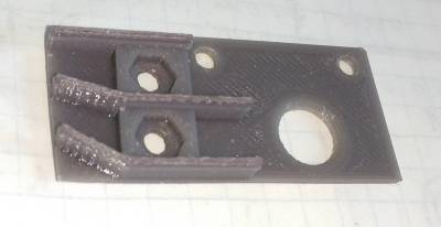
The main concern with using a cable chain for the Y-axis is how to make a connection which is both capable of sustaining high currents, can be crimped, and is small to fit into a 3d-printed enclosure. For this, a suitable option would be to use unisolated cable-shoes. These are easy to source and easy to use with a 3d printed mounting base, which functions as a junction box. On the picture below a first prototype can be seen:
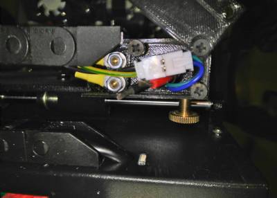
To protect the open connections, the design was improved, by adding 1mm thick walls around it:
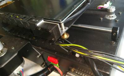
With the cover, mounted on the junction box and on the junction box mounted onto the aluminium profile, it looks like the following (click on picture to zoom):
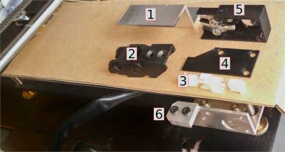
The whole combination consists of the following parts:
At the picture the following are shown:
- Aluminium Z-profile, 20x20x20, 2mm thickness, 45mm length
- Cable chain, 10x10xR18
- JST-XH connector & socket and 2-pin header to connect two sockets with each other
- Cover, to be printed
- Junction box, to be printed, with 2x M3 tapered screw, 4x M3 nut, 2x washer, 2x spring washer
- Final result of (1), including 2x M3 tapered screw (black) and 2x M3 regular screw (to mount Z-profile onto Y-base)


