Adapting anycubic main enclosure to the new PCB
The Anycubic I3 Mega enclosure needs to be slightly modified to give some space to the D-sub connectors. For this holes need to be cut in the metal casing. The following file can be helpful here:
This file contains the following drawing:

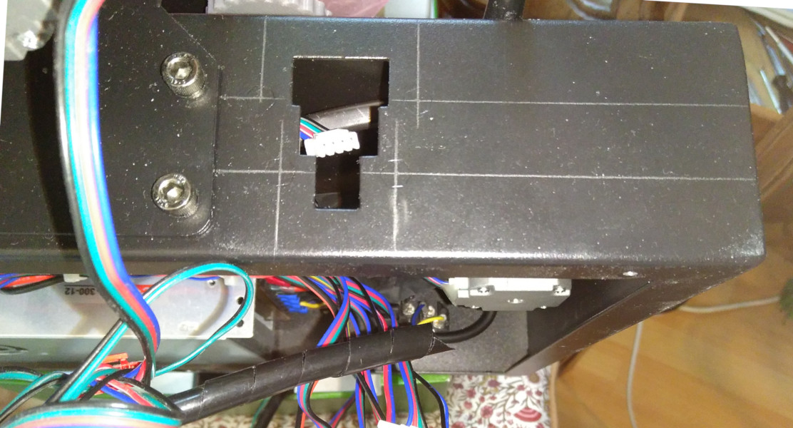
To start, first unscrew/remove everything which is attached or mounted on the main metal casing. It is better to prevent any metal dust getting onto the circuit board and/or power supply or anything else. When done, for the large cutout, draw with a pencil horizontal and vertical lines on the metal casing, using the position of the press-in nut, which is visible from the outside, like shown on the picture below:
Then place the printed drawing with some double sided sticky tape on the metal casing, using the drawn lines as guides (image below is from the 2nd iteration, but shows the same principle):
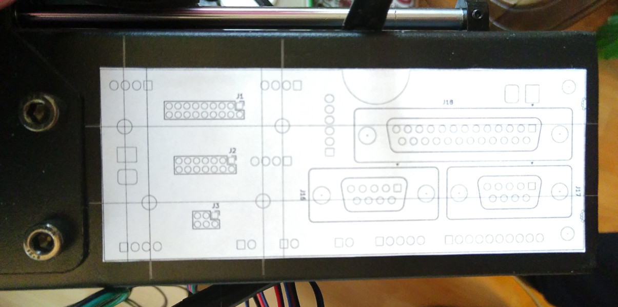
Using the printed drawing, do the following:
- Use a punch tool to mark the centre of the two holes (here visible on the right) for mounting the pcb. These need to be drilled to 3.0 mm.
- Use a sharp knife to draw lines, which mark the shape of the metal cut-out as can be seen below.
First drill the two 3.0 mm holes and counter-sink them. Then drill with a larger diameter several holes to roughly cut out the major part of the metal. Finally use a file to complete the cutout. The result should look like this:

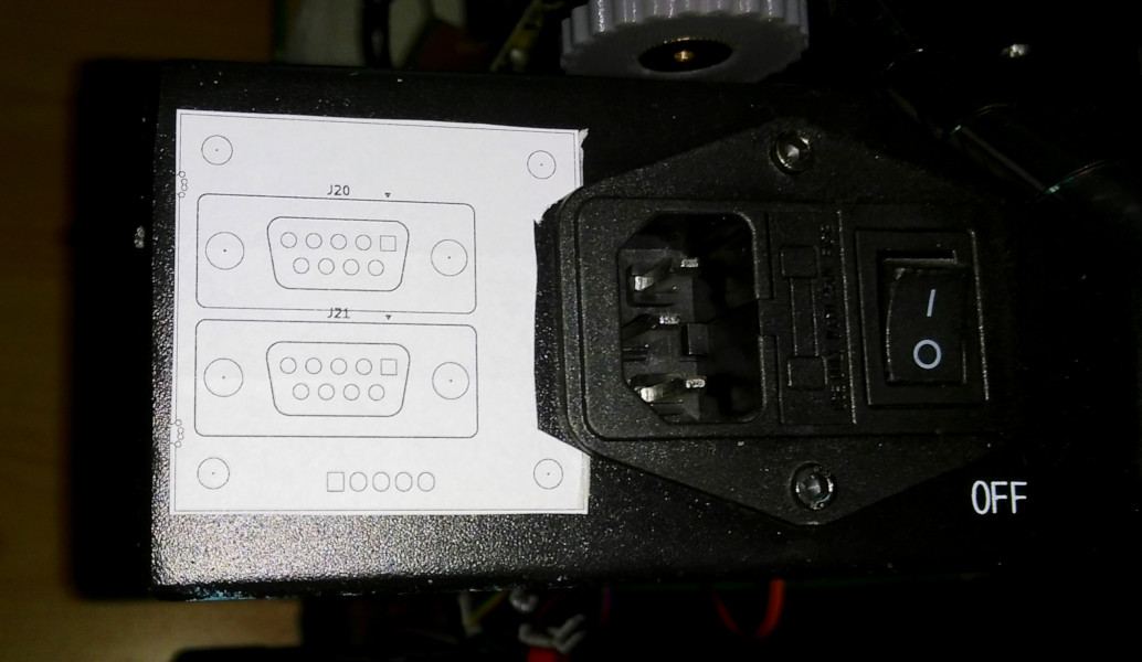
For the other side of the metal casing, the positioning is much easier, since we do not need to take into account any existing mounting points. Therefore place the drawing from above roughly as shown in the image below:
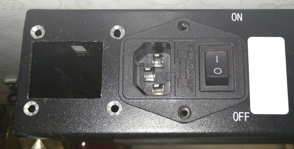
First drill the 4 holes on each side and counter-sink them. Continue with cutting with a sharp knife some lines of the cutout in the metal casing. Then use a drill to cut out the majority of the metal and use a file to finish the rectangular shape.
The result should look like the following:
Mounting circuit boards
Mount the large circuit board using the following spacers:
- 4x 2.5mm for additional distance at the 4 existing press-in nuts.
- 2x 6.0mm for the 2 mounting points at the right.
With some heat shrink and glue the 2.5mm spacers can be added more permanently to the existing press-in nuts, preventing them from falling off when trying to mount the circuit board.
The small circuit board needs 4x 6.0mm spacers for mounting.
From the inside the circuit boards should look like the following:
| Main HUB | X-stepper/Z-stepper-L |
|---|---|
 |  |
Page Tools
