This is an old revision of the document!
Table of Contents
Modifications for the ANYCUBIC I3 MEGA 3d printer
This page shows modifications for the ANYCUBIC I3 MEGA. Specifically, the following:
- How to retrofit the printer with a BLTouch leveler.
- Reverse engineer the distribution circuit board in order swap the external connectors for dsub-types.
Retrofitting the printer with a BLTouch leveler
The printer can be upgraded with an automatic leveler from BLTouch. In the following overview it is shown how this upgrade is realized within the original design. After modifying the hardware, Also software needs to be modified in order to allow the 3d printer to recognize the leveler and use it accordingly:
Hardware modification
The pins with which the BLTouch interfaces to the controller are D2 and D11. Although it would be possible to use other pins, it has become a kind of de facto standard for this printer to use these ones:
- D2 (Mega 2560, digital pin 2) for Zmin (Note that this signal has the label +X on the controller circuit board)
- D11 (Mega 2560, digital pin 11) for the control signal
To understand how to connect the leveler to the controller, the following overview shows how the signals are routed (click on pictures for larger size):
| Anycubic I3 MEGA BLTouch wiring overview | |
|---|---|
 |  |
With some larger pictures from the internal housing, the wiring looks like the following:
| Anycubic I3 MEGA internal wiring details | ||
|---|---|---|
 |  |  |
To get the correct mounting position, a bracket was designed in freecad which fits close to the extruder:
| Bracket for BLTouch | ||||
|---|---|---|---|---|
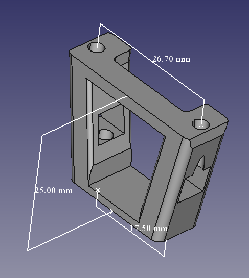 | 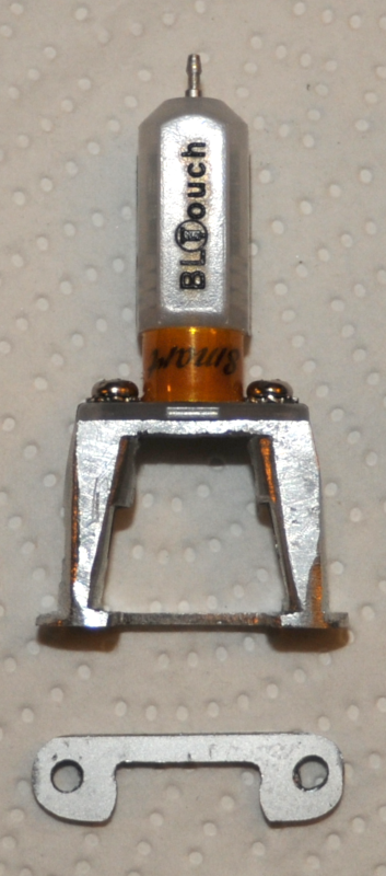 | 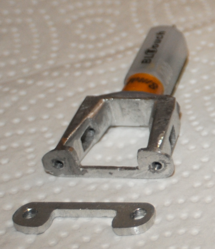 |  |  |
Please note that the shim which can be seen on the 2nd and 3rd picture was required in order to get a total distance of 25.0mm. The final design (FreeCad fcstd) is in a single piece and has this height already corrected.
At the print head a tiny strip board was added as carrier for a 3-pin jst connector. This would make it easier to separate the print head if necessary. Kapton tape was used to prevent any contact to adjacent pins. The square opening at the frame of the print head was made larger so the jst connector would also fit. Please note the difference between the last two pictures:
| Print head | |||
|---|---|---|---|
 |  |  |  |
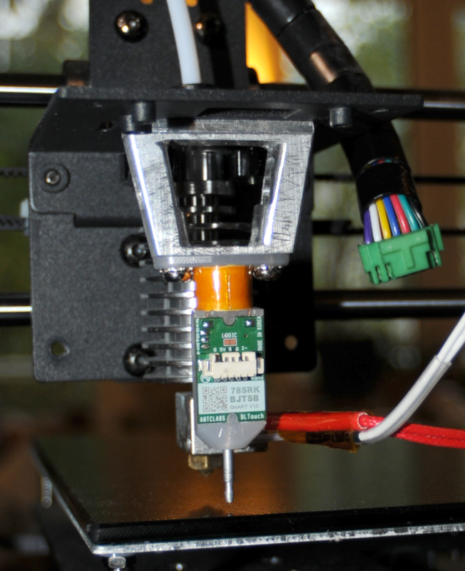
The three wires for GND, +5v and control signal are added to the main cable assembly and routed via the side where the connectors are, into the inner housing:
| External wiring and final result | ||
|---|---|---|
 |  |  |
Software modification
Distribution circuit board
The external connections of the 3d-printer are neither very robust, nor do they offer much flexibility in respect to upgrading/changing the printer. From the original distribution circuit board a new board was designed which has both the original and D-sub connectors.
The original circuit board was analyzed using a flatbed scanner:
| Anycubic I3 MEGA distribution circuit board (with and without annotation) | |
|---|---|
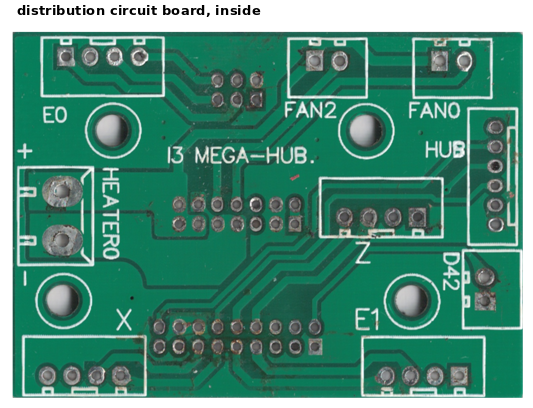 | 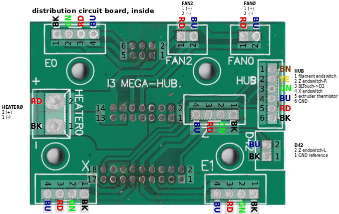 |
| anycubic_distribution_pcb.pdf | anycubic_distribution_pcb_annotated.pdf |
Then with KiCad schematics were drawn and a new circuit board was designed:
| I3 MEGA HUB-II distribution circuit board | |
|---|---|
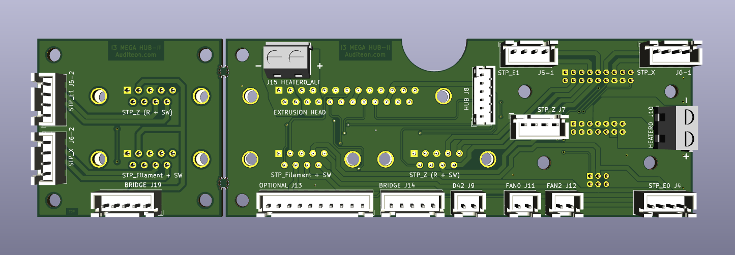 |  |
| Top | Bottom |