projects:3dprinting:flashforge_creator_3_pro_fan_fix
Table of Contents
Flashforge Creator 3 Pro - fan fix
See also: https://blog.benjojo.co.uk/post/userspace-usb-drivers
The Flashforge Creator 3 Pro printer is a dual head 3d printer, which provides pretty good printing results just out of the box and works with Linux. Although at the moment of this writing it has been just three years after product launch, Flashforge does not list the printer anymore at their official webpage. But there is still some information available on archive.org: Flashforge Creator 3 Pro.
During various tests with different filaments, I experienced that some material would stick better to the build plate than other material. Most of the time ABS would stick very well, but with PLA there were issues. Naturally one tries to change slicer settings, start a new print to verify if the change made an improvement. In this iterative approach, one of the important settings for having PLA to stick to the first layer, is to let the cooling fan cool down the extruded material. I wasn't sure whether the fans would be spinning at all, since these were hidden inside the printing enclosure and it was hard to see. Furthermore, from the display status, the fan information was not updated with the actual fan rotating speed.
What complicated matters even more was that with the official slicing software from Flashforge, Flashprint, there is a manual machine control window, which let one press buttons for “cooling fan control”. Interestingly with this feature it did not seem to be possible to control the left fan: Regardless of pressing the button for starting the left or right cooling fan here, only the right fan would actually spin. This behaviour made me initially think that this was the reason, why the filament would not stick when printing with the left extruder. I contacted Flashforge customer support about this, but after many fruitless discussions with them, it was also clear that Flashforge wasn't willing to fix anything at this printer.
So after spending considerable time on it, I at least found out that when printing from a file, both fans would actually work as expected. Measurements with an oscilloscope confirmed, that the mainboard also correctly controls speed using PWM control (Something which did not work on a Creator Pro 2, for example. See https://github.com/moonglow/flashforge_fan_fix for more information.). At that point, I had already started to reverse engineer the printers' firmware, trying to understand why one fan did not spin with the manual control in Flashprint. And it took just a few more months to create a patch, which then fixed the left cooling fan control.
Manual control in Flashprint looks like the following:
|
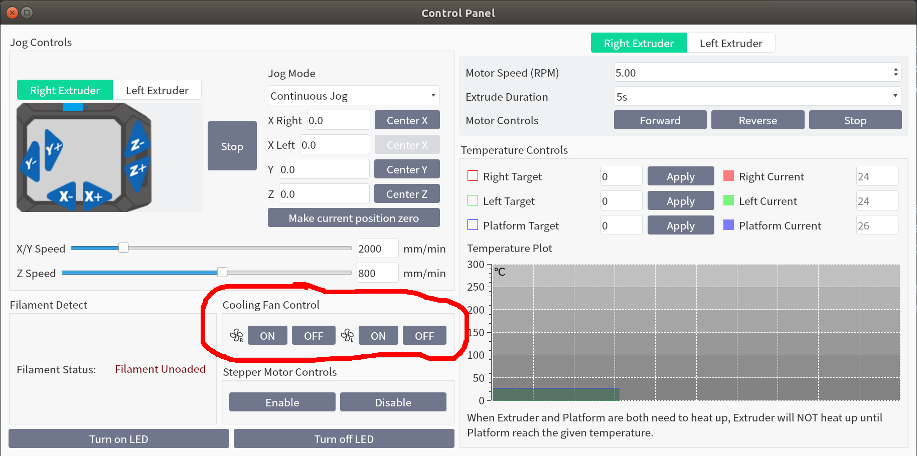
Please note the tiny little R and L character next to the fan symbol when clicking on the picture above. It is a mystery to me why Flashforge decided to place the button for the left cooling fan on the right and the button for the right cooling fan on the left. This is something probably overlooked with the software testers at Flashforge. I suspect they never had a chance to test themselves. Maybe they did not have the right hardware in front of them.
To see how the buttons should work, please see the following two video clips:
|
When these videos were sent to Flashforge customer support, they were amazed, and asked, whether these were real. I told them these were, with the only difference that the left video shows the printer with the non-patched firmware and the right videos shows the printer with the patch. As can be seen in the video, the non-patched firmware, always controls the right cooling fan, regardless of which button is clicked. With the patched firmware, it correctly controls the left or right cooling fan, depending on which button is clicked.
As explained earlier, Flashforge support was reluctant to do anything. But since I thought more people on the internet had a similar experience 1), I realized the only option was to reverse engineer its firmware and patch it. All in all, the experience was quite educational. Things like getting console access, finding relevant files, understanding ELF files, the linking process, Ghidra, Arm assembly, debugging with gdb, patching and much much more.
So if anyone plans to undertake something similar or is just curious to see how this was done, please continue reading. You may download the new installer from here:
To install, extract the archive to an empty FAT-formatted USB stick, switch off the printer and insert the USB stick and switch on. The installation should start automatically. When finished, the printer should indicate the firmware version is 1.4.1 with date 20241018. Please install at your own risk.
System Electronics
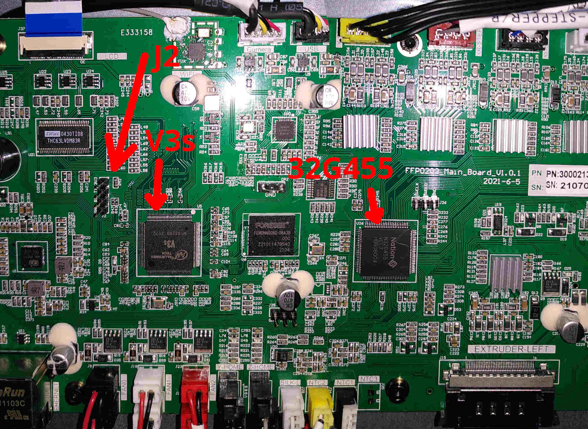
The main circuit board, mounted at the bottom, consists of two separate processors:
- Allwinner V3s with ARM Cortex A7 CPU, with integrated 64MB DDR2 RAM as main processor. (Click here to see Allwinner V3s Kernel/system boot messages.)
- Nation N32G455 with a 32-bit ARM Cortex-M4 core as motion controller. (Click here to see serial communication between main cpu and motion controller.)
|
The main role of the Allwinner cpu, apart from providing a graphical user interface, is to prepare gcode commands from internal saved files and/or commands sent over the network to the printer and forward them to the motion controller. In the other direction, the motion controller sends data, like temperature information to the main cpu. This can be seen when connecting a serial cable to the corresponding RX/TX pins (J25) on the main board.
System Software Details
The Flashforge linux based system is made with an old version of buildroot (2016), as we can see when we try to login, using a serial cable at the circuit board at connector J2:
Welcome to flashforge
buildroot login: root
Password:
Login incorrect
With the correct password, we would get an opportunity to analyze the system. It would be easier though if we can access the system with ssh. But from a port scan with nmap, it looks like there is no ssh server (dropbear) installed per default. This assumption was also confirmed later on, once we got into the system. So we would need to build dropbear ourselves first, which can be easily done using buildroot.
Either way, without a username and password we will not get access to the system. Details about getting a username and password can be found on the internet.2). You may also see following page to see what I used.
Please click on this link for more information about how to build dropbear and install it to get ssh working.
Once a terminal connection is made to the printer, and we have a chance to look at the start-up procedure and system setup, more serious reverse engineering can start. There are several great tools for reverse engineering. I highly recommend Ghidra. It is an open-source disassembler and can do a few things which make it so much easier to understand what is going on. It is able to create from the raw binary ELF file an abstract kind of C code. It automatically adds labels to variables and memory locations, is able to create function graphs which shows the flow of the code and much more.
Reverse engineering - I
The first step to understand the processes which take place upon powering up the printer is to see if there is some information provided at a serial port. With a baudrate of 115200 and connecting to J2, I could see the following excerpt (Please see here for more details and a full log)
U-Boot SPL 2017.01-rc2-00057-g32ab180-dirty (Jan 06 2021 - 10:39:41)
DRAM: 64 MiB
Trying to boot from MMC1

U-Boot 2017.01-rc2-00057-g32ab180-dirty (Jan 06 2021 - 10:39:41 +0800) Allwinner Technology

CPU:   Allwinner V3s (SUN8I 1681)
Model: Lichee Pi Zero
DRAM:  64 MiB
MMC:   SUNXI SD/MMC: 0
Setting up a 320x480 lcd console (overscan 0x0)
...
mmc0(part 0) is current device
reading script.bin
26972 bytes read in 23 ms (1.1 MiB/s)
reading uImage
3026952 bytes read in 158 ms (18.3 MiB/s)
## Booting kernel from Legacy Image at 41000000 ...
   Image Name:   Linux-3.4.39+
...
From the output, one can see, it is using U-Boot to get into Linux-3.4.39+
Once the linux kernel is loaded into memory3), linux calls /etc/init.d/rcS which at its tail contains following conditional expression to start the file /opt/auto_run.sh
...
if [ -f "/opt/auto_run.sh" ];then
        . /opt/auto_run.sh
fi
Since the file /opt/auto_run.sh is present, it is called and does then the following:
- Checks if a system update is required. For this it tries to mount an external storage. If it finds a Creator3Pro*.tgz file on it, it will extract and update the system. If the file is not present, it looks for the file flashforge_init.sh and executes that instead if present.
- Setup wifi using wpa_supplicant and a kernel module 8188fu.ko
- Setup environment variables for the cross-platform application framework qt and for the touchscreen using tslib
- Starts two processes in the background:
- /opt/mydaemon.out
- /opt/ffstartup-arm -f /opt/ffstartup.cfg
In /opt/ffstartup.cfg finally is then a reference made to our target binary:
  AppName = software/%VERSION%/creator3-arm
  AppArgs = 1;-qws
This contains a reference to the printer application which among others handles the user interface. Interestingly there are also arguments provided, from which -qws let the application use the qt windowing system. The application itself then serves as a front-end, sending commands to the motion controller, to control the printers' mechanics. The placeholder %VERSION% points to a version number formatted like: “1.4.0”. So the full path for the binary creator3-arm would be then:
/opt/software/1.4.0/creator3-arm
This is the file we need to inspect further and find if it contains any handling of commands to control the fans. For this we open the file in Ghidra.
Reverse engineering - II
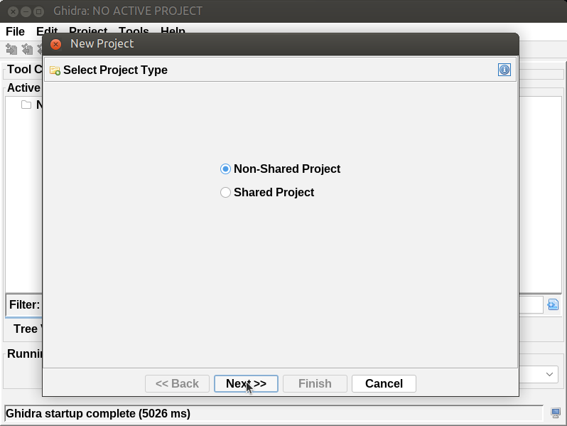
When opening creator3-arm for the first time with ghidra we need to provide some initial data, helping it with the first analysis.
|
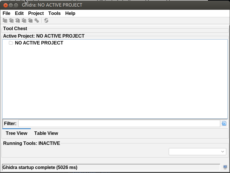
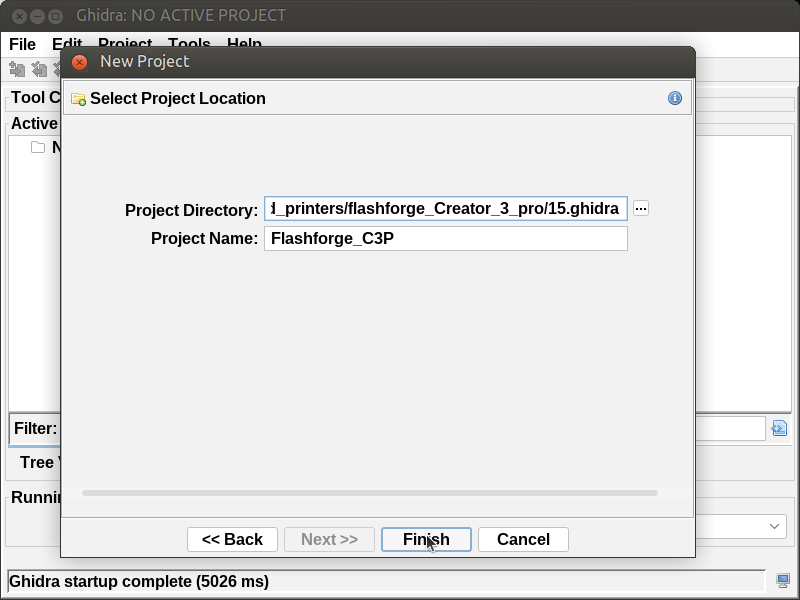
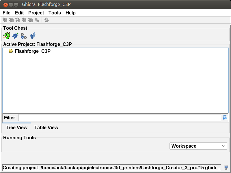
After clicking on Finish, the Flashforge_C3P Project should appear. Then start the Code Browser by clicking on the green Ghidra icon.
|
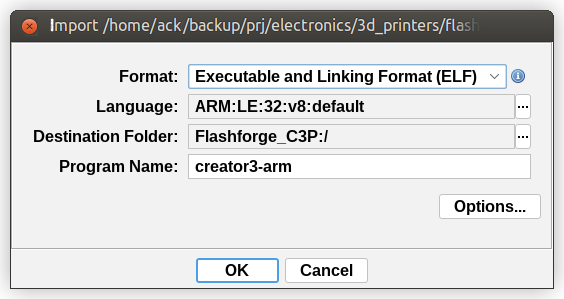
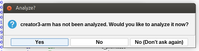
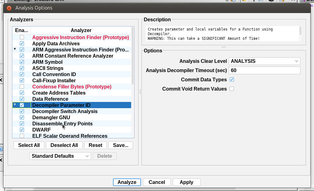
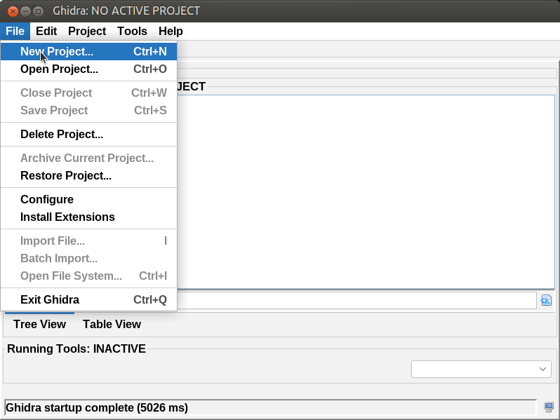
To import the creator3-arm file, click on: File → Import File… by selecting the binary and clicking on OK. After that it will ask if the file needs to be analyzed. Click on Yes and continue with configuring the analysis options: Enable the following additional options:
- ARM Aggressive Instruction Finder
- Decompiler Parameter ID
Then after showing a summary, the CodeBrowser window should appear with the disassembly and pseude c-code.
|
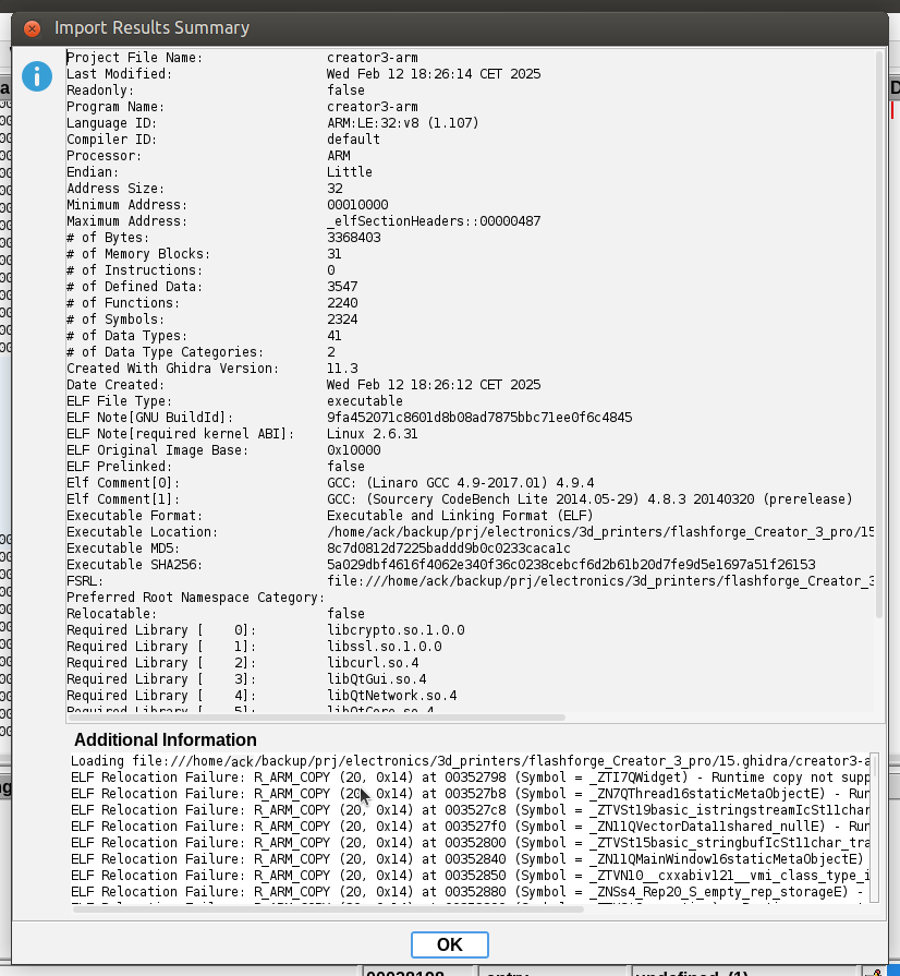
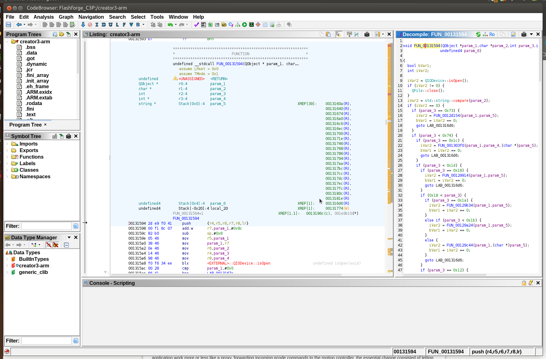
Then click on Analyze and wait for Ghidra to finish.
Reverse engineering - III
Another possibility to better understand the printer's firmware and patches, is to start creator3-arm with gdb. However, this will only work if the environment variables are correctly setup and if the application is started in gdb with the correct arguments. This is what I found:
# Terminate the following applications manually:
# /opt/mydaemon.out
# /opt/ffstartup-arm
# /opt/software/1.4.0/creator3-arm

# Find the corresponding process id's with:
ps ax

# Then kill with something like:
kill 131 132 136


# export the following variables:
export TSLIBDIR=/opt/tslib-1.4
export TSLIB_TSDEVICE=/dev/input/event0
export TSLIB_CALIBFILE=/opt/tslib-1.4/etc/pointercal
export TSLIB_CONSOLEDEVICE=none
export TSLIB_FBDEVICE=/dev/fb0
export TSLIB_TSEVENTTYPE=INPUT
export TSLIB_CONFFILE=/opt/tslib-1.4/etc/ts.conf
export TSLIB_PLUGINDIR=/opt/tslib-1.4/lib/ts
export QWS_MOUSE_PROTO="TSLIB:/dev/input/event0"
export QT_QPA_PLATFORM=linuxfb:tty=/dev/fb0:size=480x800:mmsize=225x123:offset=0
export QWS_DISPLAY=transformed:rot180:LinuxFB:mmWidth225:mmHeight123:0
export QT_QWS_FONTDIR=/opt/qt-4.8.6/lib/fonts
export QT_QPA_PLATFORM_PLUGIN_PATH=/opt/qt-4.8.6/plugins
export OPENSSLDIR=/opt/library/1.0.1/openssl-1.0.2d
export CURLDIR=/opt/library/1.0.1/curl
export LD_LIBRARY_PATH=/opt/library/1.0.1/openssl-1.0.2d/lib:/opt/library/1.0.1/curl/lib:/opt/mjpg-streamer/lib:/opt/qt-4.8.6/lib:/opt/tslib-1.4/lib:

# To prevent error from openssl: Program received signal SIGILL, Illegal instruction.
# 0xb6df7c68 in _armv7_tick ()
# from /opt/library/1.0.1/openssl-1.0.2d/lib/libcrypto.so.1.0.0
export OPENSSL_armcap=0


# Invoke gdb

  gdb /opt/software/1.4.0/creator3-arm

# Set breakpoint at entry point
  break *0x0028198

# Set additional breakpoints if necessary:
  break *0x0004e78a
  break *0x0004ea12
  ...

Verify if all breakpoints are set:
  (gdb) info b

# and run with command line arguments:

  (gdb) r 1 -qws

# Now gdb can be used as required.
Examining the main application creator3-arm
The detailed structure of ELF files is explained at many good places on the internet. I recommend the following:
When inspecting creator3-arm4) with the file command it reveals the following:
file creator3-arm
creator3-arm: ELF 32-bit LSB executable, ARM, EABI5 version 1 (SYSV),
dynamically linked, interpreter /lib/ld-linux.so.3, for GNU/Linux 2.6.31,
BuildID[sha1]=9fa452071c8601d8b08ad7875bbc71ee0f6c4845, stripped
The ELF program headers table describes to the loader how to bring the binary into memory space for execution. The table defines a series of segments, where each segment contains specific information for the kernel, like where and how to map ELF file's data into memory, whether the program needs a so-called runtime loader for bootstrapping which is done by the systems' ELF interpreter (As can be seen at the output of the file command from above: “interpreter /lib/ld-linux.so.3”), what the initial layout of the primary thread's thread-local-storage (TLS) should look like, and other kernel-relevant metadata such as whether the program should be given executable thread stacks5).
readelf --program-headers creator3-arm
Which outputs the following:
Elf file type is EXEC (Executable file)
Entry point 0x28199
There are 8 program headers, starting at offset 52

Program Headers:
    Type      Offset   VirtAddr   PhysAddr   FileSiz  MemSiz   Flg Align
    EXIDX     0x32795c 0x0033795c 0x0033795c 0x009128 0x09128  R   0x4
    PHDR      0x000034 0x00010034 0x00010034 0x000100 0x00100  R E 0x4
    INTERP    0x000134 0x00010134 0x00010134 0x000013 0x00013  R   0x1
        [Requesting program interpreter: /lib/ld-linux.so.3]
    LOAD      0x000000 0x00010000 0x00010000 0x330a88 0x330a88 R E 0x10000
    LOAD      0x331000 0x00351000 0x00351000 0x001798 0x047dc  RW 0x10000
    DYNAMIC   0x3311dc 0x003511dc 0x003511dc 0x000148 0x00148  RW 0x4
    NOTE      0x000148 0x00010148 0x00010148 0x000044 0x00044  R  0x4
    GNU_STACK 0x000000 0x00000000 0x00000000 0x000000 0x00000  RW 0x10

Section to Segment mapping:
    Segment Sections...
        00  .ARM.exidx
        01
        02  .interp
        03  .interp .note.ABI-tag .note.gnu.build-id .hash .dynsym .dynstr
            .gnu.version .gnu.version_r .rel.dyn .rel.plt .init .plt .text
            .fini .rodata .ARM.extab .ARM.exidx .eh_frame
        04  .init_array .fini_array .jcr .dynamic .got .data .bss
        05  .dynamic
        06  .note.ABI-tag .note.gnu.build-id
        07
From the output we can see this creator3-arm has nine program headers, from which the following is probably noteworthy:
- PHDR program header, which contains the program header table and its concerning metadata.
- INTERP program header, which tells the kernel that the file depends on an external loader file (/lib/ld-linux.so.3) to bring itself into memory. The other important task of the loader is that if dynamically linked libraries are used, a relocation process is done, using the global symbol table.
- LOAD program headers, tell the kernel and the loader how to get the program's data into memory. Each LOAD header directs the loader to create a region of memory with a given size, memory permissions, and alignment criteria, and tells the loader which bytes in the file to place in that region. The first LOAD header region is 0x330a88 bytes long and occupies the same size in memory, placed at virtual address 0x10000 with 64KB alignment and read + executable permissions. Given the large size, it is expected to find here the executable code which needs to be examined. Luckily, as we will see later on, the size is not using a full 64K alignment boundary, which means, that if we would need some extra space for additional code, we could increase the size until it aligns without the necessity to relocate higher adjacent regions.
- DYNAMIC program header, which is used by the loader to create links to their shared library dependencies. It is also used by the loader to fix relocations for program code and pointers, if the program resides at a different place in memory than it expects based on its virtual address.
- NOTE program header potentially contains vendor-specific metadata about the program itself, describing a table of key-value pairs where each entry has a string name mapped to a sequence of bytes that describe the entry.
- GNU_STACK program header defining memory regions where the stack is marked with a no-execute flag. With this flag code cannot be executed if it is on the stack.
The section headers, in contrast to the program headers, describe in more detail how the ELF file is divided into logical units. To get more information about the ELF sections, we use:
readelf --section-headers creator3-arm
which outputs the following:
There are 29 section headers, starting at offset 0x332934:
Section Headers:
  [Nr] Name              Type            Addr     Off    Size   ES Flg Lk Inf Al
  [ 0]                   NULL            00000000 000000 000000 00      0   0  0
  [ 1] .interp           PROGBITS        00010134 000134 000013 00   A  0   0  1
  [ 2] .note.ABI-tag     NOTE            00010148 000148 000020 00   A  0   0  4
  [ 3] .note.gnu.build-i NOTE            00010168 000168 000024 00   A  0   0  4
  [ 4] .hash             HASH            0001018c 00018c 0021ac 04   A  5   0  4
  [ 5] .dynsym           DYNSYM          00012338 002338 004830 10   A  6   1  4
  [ 6] .dynstr           STRTAB          00016b68 006b68 0081ae 00   A  0   0  1
  [ 7] .gnu.version      VERSYM          0001ed16 00ed16 000906 02   A  5   0  2
  [ 8] .gnu.version_r    VERNEED         0001f61c 00f61c 000130 00   A  6   5  4
  [ 9] .rel.dyn          REL             0001f74c 00f74c 000160 08   A  5   0  4
  [10] .rel.plt          REL             0001f8ac 00f8ac 001fe8 08   A  5  12  4
  [11] .init             PROGBITS        00021894 011894 00000c 00  AX  0   0  4
  [12] .plt              PROGBITS        000218a0 0118a0 003098 04  AX  0   0  4
  [13] .text             PROGBITS        00024938 014938 1a863c 00  AX  0   0  8
  [14] .fini             PROGBITS        001ccf74 1bcf74 000008 00  AX  0   0  4
  [15] .rodata           PROGBITS        001ccf80 1bcf80 13b5d4 00   A  0   0  8
  [16] .ARM.extab        PROGBITS        00308554 2f8554 02f408 00   A  0   0  4
  [17] .ARM.exidx        ARM_EXIDX       0033795c 32795c 009128 00  AL 13   0  4
  [18] .eh_frame         PROGBITS        00340a84 330a84 000004 00   A  0   0  4
  [19] .init_array       INIT_ARRAY      00351000 331000 0001d4 00  WA  0   0  4
  [20] .fini_array       FINI_ARRAY      003511d4 3311d4 000004 00  WA  0   0  4
  [21] .jcr              PROGBITS        003511d8 3311d8 000004 00  WA  0   0  4
  [22] .dynamic          DYNAMIC         003511dc 3311dc 000148 08  WA  6   0  4
  [23] .got              PROGBITS        00351324 331324 001008 04  WA  0   0  4
  [24] .data             PROGBITS        0035232c 33232c 00046c 00  WA  0   0  4
  [25] .bss              NOBITS          00352798 332798 003044 00  WA  0   0  8
  [26] .comment          PROGBITS        00000000 332798 00006a 01  MS  0   0  1
  [27] .ARM.attributes   ARM_ATTRIBUTES  00000000 332802 000031 00      0   0  1
  [28] .shstrtab         STRTAB          00000000 332833 000101 00      0   0  1
Key to Flags:
  W (write), A (alloc), X (execute), M (merge), S (strings), I (info),
  L (link order), O (extra OS processing required), G (group), T (TLS),
  C (compressed), x (unknown), o (OS specific), E (exclude),
  y (purecode), p (processor specific)
For clarity some sections have been left out. Most of the time the following sections are interesting for reverse engineering:
- .interp
- .text
- .rodata
- .bss
- .shstrtab
Questions I was confronted with were, rather how relocation happens upon linking process at startup, where in the file is it possible to put these patches and what can be done, if there is no space available (if the original code does not have any free area where to place the patched code.).
There are many great webpages and books available on this topic.6).
Information about assembly, linker and linker scripts was very valuable as well7). The process to create binary files from assembly files, stripping the library and ultimately patch firmware by overwriting it.
The debugger gdb, which makes it possible to test the software and see if patches have some effect is installed at the printer.
Then, after understanding enough about the system, I was finally able to create a fix for the M106 and M107 commands. This was done by reusing the existing implementations of the M104 and M108 commands, adapting them for M106 and M107. Because the gcode functions in the main application work more or less like a proxy, forwarding incoming gcode commands to the motion controller, the essential change consisted of letting pointers in the M104 and M108 functions point to other memory locations where the characters 'M106' and 'M107' were present.
Then all what was basically necessary was to overwrite the existing M106 and M107 functions.
Because the new M106 function was larger than the original, it could not be placed at the original memory location. There all the studying about ELF files paid out well, because I discovered that due to memory alignment considerations at the end of the .text segment, there was just enough space to place the new M106 function. The new M107 function also was larger, but I was able to put that at the original M106/M107 memory location.
When looking at the program headers in the ELF file, we can see the following information:
  Start of program headers:          52 (bytes into file)
  Size of this header:               52 (bytes)
  Size of program headers:           32 (bytes)
  Number of program headers:         8
Then, when looking at the all of the eight program headers, and verifying the permissions at the p-flags, only program header 3 ist executable and contains the actual program.
# program header 3
00000094: 0100 0000 0000 0000 0000 0100 0000 0100  ................
000000a4: 880a 3300 880a 3300 0500 0000 0000 0100  ..3...3.........
p_type:   (4 bytes) PT::LOAD
p_offset: (4 bytes) 0x000000 (      0)
p_vaddr:  (4 bytes) 0x010000 (  65536)
p_paddr:  (4 bytes) 0x010000 (  65536)
p_filesz: (4 bytes) 0x330a88 (3345032)
p_memsz:  (4 bytes) 0x330a88 (3345032)
p_flags:  (4 bytes) X | R
p_align:  (4 bytes) 0x010000 (  65536)
p_data:   0x00 - 0x330a87 (3345032 bytes)
Interestingly this program header has a p_align of 65536 bytes, which means that at the end 1398 bytes should be available:
With a hex Editor one can observe that this area indeed is filled with 0x00: From 0x330a88 to 0x330fff (3345032 - 3346431 = 1399 bytes)
With that it should be possible to inject Code from the M104 command (979 bytes) into this area and adapt for the M106 command.
Flashprint Wireshark
When clicking a button in Flashprint to start or stop a fan, a network command is sent to the printer, which can be captured with tcpdump and analyzed with wireshark. Interestingly, Flashprint does actually differentiate between the left and right cooling fan by sending also the index to the printer. It is just looks like the printer does not interpret that parameter.
For further debugging, it is much easier to directly send a command to the printer than using Flashprint. We can use the tool netcat for this.
The command to set the right (index 0) or left (index 1) fan to full speed using netcat would be:
echo "~M106 S255 T0" | nc -N printer.localhost 8899
echo "~M106 S255 T1" | nc -N printer.localhost 8899
(Where printer.localhost is resolved into the address of the Flashforge 3d printer.)
The printer returns an acknowledgement:
CMD M106 Received.
Debug mode
From analysis of the rootfs, the main application (creator3-arm) would always be started with the command line options “1 -qws”:
creator3-arm 1 -qws
But after analyzing with ghidra, I saw, there is also a -debug option, which, when used, reveal many interesting messages on the terminal. These look like:
...
serial/SerialObject.cpp serialSendCode 415 "G90"
serial/SerialObject.cpp serialSendCode 415 "G92 A0 B0"
serial/SerialObject.cpp serialSendCode 415 "M140 S50"
serial/SerialObject.cpp serialSendCode 415 "M104 S200 T0"
serial/SerialObject.cpp serialSendCode 415 "M104 S0 T1"
Execute/onetimesclicked.cpp setOneTimesClicked 37
UI/buildprint.cpp on_stop_pressed 1038
UI/mainwindow.cpp dialogTwoButtonClose 732
Dialog/twobuttondialog.cpp TwoButtonDialog 25 title= "Cancel print job" text= "Are you sure?" okText= "Yes" backText= "No"
Execute/onetimesclicked.cpp slot_oneTimesClicked 47
Execute/onetimesclicked.cpp setOneTimesClicked 37
Dialog/twobuttondialog.cpp on_ok_pressed 84
...
We can see in the snippet above, that there is a function serialSendCode which sends various commands to the Nation N32G455 (ARM Cortex-M4). The interesting thing with this, is that we can see exactly what is sent to the N32G455.
Without deep understanding yet of the inner workings, I noticed the M104 function in comparison, did send more arguments to the Nation N32G455 chip. As an experiment, I changed the string “M104” in “M106” in the binary and noticed that when sending the M104 command using netcat, the main processor would send M106 instead to the Nation N32G455, with the arguments which I provided: The left fan started spinning for the first time!
With that, a possible fix was found: Function M104 could be cloned and used to handle M106.
Not much later, while inspecting with ghidra, I found the large switch-case statement where all gcode commands are evaluated. For M106 the relevant address is at 0x131620 and for M104 it is at 0x13170e:
...
LAB_00131618:   XREF[1]:     001315c8(j)
    00131618 1c 2c           cmp        r4,#0x1c
    0013161a 00 f0 26 81     beq.w      LAB_0013186a
    0013161e 32 dd           ble        LAB_00131686
    00131620 6a 2c           cmp        r4,#0x6a          @ r4 = 106  <--- M106
    00131622 00 f0 55 81     beq.w      LAB_001318d0
    00131626 72 dd           ble        LAB_0013170e
    00131628 6c 2c           cmp        r4,#0x6c
    0013162a 00 f0 48 81     beq.w      LAB_001318be
    0013162e c0 f2 d4 80     blt.w      LAB_001317da
    00131632 70 2c           cmp        r4,#0x70
    00131634 00 f0 33 81     beq.w      LAB_0013189e
    00131638 72 2c           cmp        r4,#0x72
    0013163a 40 f0 95 80     bne.w      LAB_00131768
...
LAB_0013170e    XREF[1]:        00131626(j)
    0013170e 68 2c           cmp        r4,#0x68          @ r4 = 104  <--- M104
    00131710 00 f0 83 80     beq.w      LAB_0013181a
...
And M106 is further handled at LAB_001318d0:
LAB_001318d0    XREF[1]:        00131622(j)
    001318d0 28 46           mov        param_1,r5
    001318d2 08 99           ldr        param_2,[sp,#param_5]
    001318d4 f8 f7 2c fe     bl         FUN_0012a530    undefined FUN_0012a530()
    001318d8 b0 fa 80 f0     clz        param_1,param_1
    001318dc 40 09           lsrs       param_1,param_1,#0x5
    001318de fa e6           b          LAB_001316d6
At LAB_001318d0, parameters param_1 (Which goes to r0) and param_2 (to r1) are set, before calling the rest of M106 at FUN_0012a530. The calling convention for handling over parameters in c functions in arm architecture is not by placing them on the stack, but using r0, r1, r2 and r3 instead for the first 4 registers.
For comparison, the parameter preparation for M104 at LAB_0013181a takes one argument more and looks like:
LAB_0013181a    XREF[1]:        00131710(j)
    0013181a 41 46           mov        param_2,r8
    0013181c 28 46           mov        param_1,r5
    0013181e 08 9a           ldr        param_3,[sp,#param_5]
    00131820 fb f7 bc f9     bl         FUN_0012cb9c    undefined FUN_0012cb9c()
    00131824 b0 fa 80 f0     clz        param_1,param_1
    00131828 40 09           lsrs       param_1,param_1,#0x5
    0013182a 54 e7           b          LAB_001316d6
This means that to be able to re-use the function M104, not only function M104 needs to be copied but also the parameter preparation for M104.
Like M106, the original M107 gcode command would ignore the index as argument. So neither “M107 T0”, nor “M107 T1” would make any difference. And instead it would always only stop the right fan.
So in order to fix this, with the understanding of the fix for the M106 function, we just need to clone an available function, which is able to handle an index as argument and modify this for M107. For this, the function M108 was used.
patching creator3-arm
The arm binary needed to be patched at several locations. During debugging and development, a script was written which takes a csv file containing target addresses, references to .s assembly files and assembles them. And place the resulting binaries into the original file. The .csv file which was used for creating 1.4.1 looks like the following:
0x0100a4;"src/ELF_FileSiz_MemSiz.s";"Max out ELF .text section size from alignment provision"
0x1318d0;"src/m106_args_preparation.s";"Fix function argument handling for function M106"
0x330a88;"src/m106_fun.s";"Fix function M106"
0x1317da;"src/m107_args_preparation.s";"Fix function argument handling for function M107"
0x12a530;"src/m107_fun.s";"Fix function M107"
0x1d437c;"src/bump_up_version.s";"bump up software version from 1.4.0 to 1.4.1"
0x1d4370;"src/bump_up_date.s";"modify software creation date from 20230201 to 20241018"
Here column 1 contains the address where to place the binary file. This is the so-called VirtAddress of the code in memory and starts at 0x10000. To calculate the position where to place the code at the file, it is necessary to subtract 0x10000 from the address.
Column 2 contains the Gnu as assembly .s file which needs to be assembled. Most of the code was copied from Ghidra and rewritten by hand to be compatible to Gnu as. To resolve the labels into addresses, the opcode was taken and looked up with the online tool armconverter.
Column 3 contains an arbitrary description which is shown when running the script.
The script itself has the sha256 embedded of the 1.4.0 target file and will only continue when it matches. The heavy lifting is done with the following tools:
- arm-linux-gnueabihf-as to assemble the .s file into .o object file for thumb.
- arm-linux-gnueabihf-ld linker to relocate the object file to an elf file with a certain target address.
- arm-linux-gnueabihf-objcopy to extract only the .text section from the object file and convert the relocated elf file into a binary file, resulting in a file only containing the assembled instructions without any overhead.
- dd to overwrite (using conv=notrunc) the existing code with the binary file
Download firmware 1.4.0
The latest official firmware from Flashforge (Februar 2023) is version 1.4.0.
1)
See for example here https://forum.simplify3d.com/viewtopic.php?t=23171 and https://forum.simplify3d.com/viewtopic.php?t=23370
4)
Version 1.4.0
5)
ARM ASSEMBLY, Internals & Reverse Engineering, Maria Markstedter, Wiley, 2023
6)
See for example:
https://cirosantilli.com/elf-hello-world,
https://www.youtube.com/watch?v=E804eTETaQs&t=43s,
https://www.youtube.com/watch?v=eQ0KOT_J8Sk,
https://lwn.net/Articles/631631/,
https://www.gabriel.urdhr.fr/2015/09/28/elf-file-format/,
https://stevens.netmeister.org/631/elf.html,
https://jvns.ca/blog/2014/09/06/how-to-read-an-executable/,
https://ktln2.org/2019/10/28/elf/,
https://github.com/TheThirdOne/elf-edit/,
https://blog.elfy.io/,
https://pokology.org/fun-with-elf.html,
https://thenybble.de/posts/modifying-elf-dependency-versions/,
https://github.com/fimad/Keebler,
https://gist.github.com/CMCDragonkai/10ab53654b2aa6ce55c11cfc5b2432a4,
http://blog.k3170makan.com/2018/09/introduction-to-elf-format-part-ii.html and
https://www.wiley.com/en-dk/Blue+Fox%3A+Arm+Assembly+Internals+and+Reverse+Engineering-p-9781119745303
projects/3dprinting/flashforge_creator_3_pro_fan_fix.txt · Last modified: 2025/05/02 22:57 by admin
Page Tools
Except where otherwise noted, content on this wiki is licensed under the following license: CC Attribution-Noncommercial-Share Alike 4.0 International
