projects:tesla_car:doorhandles
Table of Contents
Tesla Model S door handles
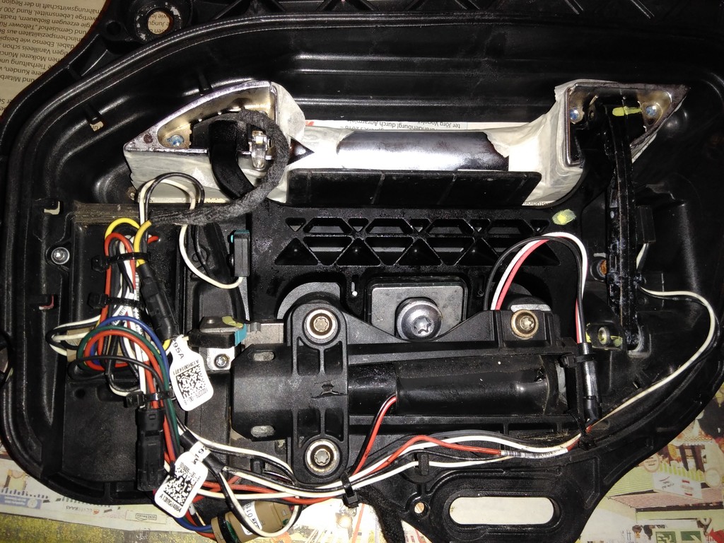
Until about 2017, the Model S door handles suffered two problems. These were:
- Water ingress damaged multiple parts. These were:
- Circuit board with the controller.
- Some wires which protrude at connectors got corrosion directly at the exit with green from copper-like color.
- The axis of the gear at the gear box, which stuck in the plastic housing was corroded.
- Missing grease around the gear, probably because soapy water drained all away.
- Broken wires at a moving switch which was mounted at the arm.
- Non working LED illumination module was probably hammered in by Tesla, which caused cracks in the plastic with water ingress and corrosion as a consequence.
Remedy RR-RH
Original part after taking out:
A solution for the switches was to combine both moving switches in a stationary holder. After designing with FreeCAD, the following came out:
Mylar sheet
One of the objectives is to make the doorhandles water-proof. For this the following material has been tested:
- IASOPET OAN 26μm, Zolltarif PET Folie 39206219, BOPP Folie 39202021 (delivered from the company Strohmeier+Ernst GmbH & Co KG, Pilgerplatt 10, 33378 Rheda-Wiedenbrück, Mr. Gottlieb Ernst, Tlf. 05242-406603, Kunde Nr. 500002)
- Hostaphan RNT/36μm, (Delivered by the company Pütz GmbH + Co. Folien KG, Obere Waldstr. 26 + 26a, 65232 Taunusstein-Wehen, Tlf. Mrs. Manuela Erdmann, Tlf. 06128-964270)
FreeCad
The following script creates the RR_RH part:
#!/usr/bin/python
# This script creates a small 3d printable enclosure for two switches
# to improve the constuction of a tesla retracting door handle.
#
# copyright: Marc Nijdam
# Date of creation: 05.02.2018
#

# To run this independent of an instance of freecad, uncomment following lines.
#import sys
#sys.path.append("/usr/lib/freecad/lib")
#import FreeCAD
#import FreeCADGui
# Otherwise, copy paste this code into the freecad python console.

import WebGui
import PartDesignGui
import math
import Part
import os.path

# helper functions

# sketches a line from a to b on a sketch object: App.getDocument("tesla_RR_RH").some_sketch
def sketch_line(pl_obj,a,b):
	return pl_obj.addGeometry(Part.LineSegment(App.Vector(a[0],a[1]),App.Vector(b[0],b[1])),False)

# returns sum of two coordinates
def addp(a,b):
	return ([a[0] + b[0], a[1] + b[1]])

#
# coordinate system
#     ________
#    !       \_
#    !         !
#    !         !
#  ^ !     ____!
#  y !_(o)!
#
#    x >
#
# creation mode: 0:final shape, 1:3d printable shape
print_3d = 1
# parameters: stack
hb = 2.0 # height of bottom area
hb1 = 4.0 # thickness of base 1
hb_mid = 4.0 # thickness of base_mid
# parameters: wall thickness
#     _____
#    !    !##2##
#    !    !1   3
#    !    !##4##
#  ^ !     ____!
#  y !_(o)!
#
#    x >
tw1 = 1.8 # thickness wall 1
tw2 = 1.0 # thickness wall 2
tw3 = 1.8 # thickness wall 3
tw4 = 1.8 # thickness wall 4
# parameters: switch Panasonic ASQ10410
sw_dim = [5.4, 13.3, 12.3] # switch (W x L x H)
sw_area = [13.4, 10.0, hb] # left bottom area where switches are [x,y,z]
sw_offset = [2.71, 6.66, 7.25] # offset for switch left bottom front corner
sw_rotation = [90, 0, 90] # default rotation angle for importing switch
sw_gap = 0.1 # extra margin around switch
bc_vpos = 3.2 # bottom corner vertical space
#
#  (switch side view)
#
#               _^_
#              !  !
#             #####___-----
#             !           !
#             !           !
#             ! ()     {} !    () pin     {} hole
#             !___________!
#               #   #   #
# left bottom ^
# corner is reference point (0,0)
#
sw_pin = [2.7, 7.2] # position of pin referenced to left bottom corner
pin_d = 3.0 # diameter of side pins at switches
pin_p = 1.5 # sideways distance of protruding pin
sw_hole = [2.7 + 8.3, 7.2] # position of hole referenced to left bottom corner
#
#     (switches top view)
#    _..__  _
#   [_<>__||_] SW1: Width: 13.3, pin: 2.7, pin > hole: 8.3, rest: 2.3
#     ''__.._
#    [||__<>_] SW2: Width: 13.3, hole: 2.3, hole > pin : 8.3, rest: 2.7, D_hole-right border = 13.3-2.3 = 11.0
#         ''
# Total width for reciprocal switch mounting: 2.7 + 11.0 = 13.7mm = sw_pin[0] + (sw_dim[1] - (sw_dim[1] - sw_hole[0]))
#  = sw_pin[0] + sw_hole[0]
# Therefore y dimension of wall 2 to position in sw_area = max(sw_dim[1], sw_pin[0] + sw_hole[0])
sw_fname = "/home/mni/Backup/projects/programming/freecad/tesla_adapter_pieces/asq10410.step" # file obtained from Panasonic
# parameters: mounting hole position
mnt_pos = [10.0, 5.0] # [x,y]
mnt_hole1 = 10.0 # diameter of hole at base 1
mnt_hole2 = 3.0 # diameter of hole at base 2
# parameters: total object size
obj_dim = [26.0, 26.0, sw_dim[2] + hb + sw_gap] # maximum dimensions of object
# parameters: pipe dimensions
w_trench = 2.5 # diameter of trench for cable
# parameters: small corner to cut away
crn_dim = [3.0, 1.5, obj_dim[2]] # small corner to cut material away
crn_c_angle = 88 # ref drawing 9b
# Screwhead
screw_head_d = 4 # screwhead diameter

### deriving points
#
# calculations based on choniometrical identities
# Using:
#   w_trench: closest distance between two (parallel) lines PQ and MN
#   w       : closest wall thickness (distance between lines HG and QP, FG and PN, MN and EF)
#   point F is pivot point
#   point A, B, C, D, F, I, J, K and L are fixed points.
#   other points depend on value of w and w_trench.
#   Point X is in the middle, between point I and L
#
#   Line PS is perpendicular to line MN (drawing is not to scale)
#     _________________________
#    !                        B----------------------------------C
#    !                        |                                  |
#    !                        |  J---------------------------K   |
#    !                        |  |                           |   |
#    !                        |  |                           |   |
#    !                        |  |                           |   |
#    !                        |  |                           |   |
#    !                        |  |                           |   |
#    !                        |  |                           |   |
#    !                        |  I------Q     X     M----S---L   T
#    !                        |          \     .    \     \      |
#    !                        A-----H     \     .    \     E-----D
#    !                               \     \     .    \V    W
#    !                                \     \     U    \     \
#    !                                 \     \     .    \     \
#    !                                  \     P-----.----N     \
#    !                                   \           .          \
#    !              (0)       ____________G-----------Z----------F
#    !                       )
#    !                     _/
#    !---------------------
#                                    (Drawing 4 - wall)
#
#
#
#
#   Additionally helper points U, V and W are defined, as well as T
#   Calculation is based on defining helper line XZ, parallel to SF.
#   In the middle between points U and W, is point V, which is also
#   the middle point between points X and F. The line UW is perpendicular
#   to line XZ. Furthermore, the distance of the line:
#     UW = 0.5 * w_trench + w
#   Therefore the distance of points UV is m = 0.5 * UW
#   With that we can calculate the angles a and b which we use to calculate
#   the coordinates of the remaining points.
#
sw_width = max(sw_dim[1], sw_pin[0] + sw_hole[0]) # maximum width (in y-direction) for two reciprocal positioned switches
Xmax = min(sw_area[0] + sw_dim[0] * 2 + tw3, obj_dim[0]) # Make sure, wall thickness never exceed maximum object size
Ymax = min(sw_area[1] + sw_width + tw2, obj_dim[1]) # Make sure, wall thickness never exceed maximum object size
w = max(max(max(tw1,tw2),tw3),tw4) # find the thickest wall as base to create strong walls around the wire trench
m = (0.5 * w_trench + w) * 0.5
XV = math.sqrt( ((obj_dim[0] - sw_area[0] - sw_dim[0]) / 2) ** 2 +  ((sw_area[1] - bc_vpos) / 2) ** 2)
a = math.asin(m/XV) # in radians
b = math.asin( (sw_area[1] - bc_vpos) / (XV * 2) ) # in radians
wh_trench = w_trench / math.sin(a + b)
wh = w / math.sin(a + b)

# outer wall
pt_a = [sw_area[0] - tw1, sw_area[1] - tw4] # starting point
pt_b = [sw_area[0] - tw1, Ymax]
pt_c = [Xmax, Ymax]
pt_d = [Xmax, sw_area[1] - tw4]
pt_f = [obj_dim[0], bc_vpos]
pt_x = [sw_area[0] + sw_dim[0], sw_area[1]]
pt_e = [obj_dim[0] - (sw_area[1] - tw4 - bc_vpos) / math.tan(a + b), sw_area[1] - tw4]
pt_g = addp(pt_f, [ - (2 * wh + wh_trench), 0])
pt_h = [pt_g[0] - (pt_f[0] - pt_e[0]), pt_a[1]]

# inner wall
pt_i = [sw_area[0], sw_area[1]]
pt_j = addp(pt_b, [tw1, -tw2])
pt_k = addp(pt_c, [-tw3, -tw2])
pt_l = addp(pt_d, [-tw3, tw4])
pt_m = addp(pt_x, [wh_trench/2, 0])
pt_n = [pt_m[0] + (sw_area[1] - bc_vpos - w) / math.tan(a + b), bc_vpos + w]
pt_p = addp(pt_n, [-wh_trench, 0])
pt_q = addp(pt_m, [-wh_trench, 0])

# Initialization
App.newDocument("tesla_RR_RH")
App.setActiveDocument("tesla_RR_RH")
App.ActiveDocument=App.getDocument("tesla_RR_RH")
Gui.ActiveDocument=Gui.getDocument("tesla_RR_RH")
App.activeDocument().saveAs("/home/mni/Backup/projects/programming/freecad/tesla_adapter_pieces/rear_right_side6.fcstd")
ad = App.getDocument("tesla_RR_RH")
gd = Gui.getDocument("tesla_RR_RH")

# 0. Create grid (key g, key r), set camera position
Gui.activateWorkbench("DraftWorkbench")
gd.activeView().setCamera('#Inventor V2.1 ascii \n OrthographicCamera {\n viewportMapping ADJUST_CAMERA \n position 0 0 87 \n orientation 0 0 1  0 \n nearDistance -112.88701 \n farDistance 287.28702 \n aspectRatio 1 \n focalDistance 87 \n height 143.52005 }')

# 1. Create sketch for ground object
#     _____
#    !####!
#    !####!
#    !####!_____
#  ^ !#########!
#  y !#(o)!
#
#    x >
r = mnt_hole1/2.0
q = 8.2 # bottom corner horizontal space
a1=-math.asin((mnt_pos[0]-q)/r) # starting angle of arc
a2=-math.pi/2 - math.asin((mnt_pos[0]-q)/r) # end angle of arc
xa1=mnt_pos[0] + math.sqrt(r ** 2 - (mnt_pos[1]-bc_vpos) ** 2)
ya2=mnt_pos[1] - math.sqrt(r ** 2 - (mnt_pos[0]-q) ** 2)
Gui.activateWorkbench("PartDesignWorkbench")
ad.addObject('PartDesign::Body','sw_housing_RR_RH')
ad.sw_housing_RR_RH.newObject('Sketcher::SketchObject','base_sketch')
ad.base_sketch.Support = (ad.XY_Plane, [''])
ad.base_sketch.MapMode = 'FlatFace'
Gui.activateWorkbench('SketcherWorkbench')
ActiveSketch = ad.getObject('base_sketch')
so=ad.base_sketch # sketch object
gd.setEdit('base_sketch')
sketch_line(so, [0.0, 0.0]                          , [0.0, obj_dim[1]])
sketch_line(so, [0.0, obj_dim[1]]                   , [sw_area[0] - tw1, obj_dim[1]])
sketch_line(so, [sw_area[0] - tw1, obj_dim[1]]      , [sw_area[0]-tw1, sw_area[1]-tw4])
sketch_line(so, [sw_area[0] - tw1, sw_area[1] - tw4], pt_h)
sketch_line(so, pt_h, pt_p)
sketch_line(so, pt_p, pt_n)
sketch_line(so, pt_n, pt_e)
sketch_line(so, pt_e, [obj_dim[0], sw_area[1]-tw4])
sketch_line(so, [obj_dim[0], sw_area[1]-tw4]    , [obj_dim[0], bc_vpos])
sketch_line(so, [obj_dim[0], bc_vpos]           , [xa1, bc_vpos])
so.addGeometry(Part.ArcOfCircle(Part.Circle(App.Vector(mnt_pos[0],mnt_pos[1]),App.Vector(0,0,1), r),a2,a1),False)
sketch_line(so, [q, ya2], [q, 0.0])
sketch_line(so, [q, 0.0], [0.0, 0.0])
so.addGeometry(Part.Circle(App.Vector(mnt_pos[0],mnt_pos[1]),App.Vector(0,0,1), mnt_hole2/2.0),False)
ad.recompute()
# ... pad base_sketch
Gui.activateWorkbench('PartDesignWorkbench')
ad.sw_housing_RR_RH.newObject("PartDesign::Pad","base")
ad.base.Profile = so
ad.base.Length = hb1 + hb_mid
ad.base.Length2 = 100.000000
ad.base.Type = 0
ad.base.UpToFace = None
ad.base.Reversed = 0
ad.base.Midplane = 0
ad.base.Offset = 0.000000
gd.setEdit('base', 0)
Gui.Selection.clearSelection()
gd.base.ShapeColor=gd.sw_housing_RR_RH.ShapeColor
gd.base.LineColor=gd.sw_housing_RR_RH.LineColor
gd.base.PointColor=gd.sw_housing_RR_RH.PointColor
gd.base.Transparency=gd.sw_housing_RR_RH.Transparency
gd.base.DisplayMode=gd.sw_housing_RR_RH.DisplayMode
so.ViewObject.Visibility=False
ad.recompute()
gd.resetEdit()

# 2. create maximum size floor under switch area and pad
#     _____
#    !    !#####
#    !    !#####
#    !    !#####
#  ^ !     ____!
#  y !_(o)!
#
#    x >
gd.activeView().viewAxonometric()
ad.sw_housing_RR_RH.newObject('Sketcher::SketchObject','floorbase')
ad.floorbase.Support = (ad.XY_Plane, [''])
ad.floorbase.MapMode = 'FlatFace'
Gui.activateWorkbench('SketcherWorkbench')
ActiveSketch = ad.getObject('floorbase')
bs=ad.floorbase
gd.setEdit('floorbase')
sketch_line(bs, [sw_area[0]-tw1, sw_area[1]-tw4], [sw_area[0]-tw1, obj_dim[1]    ])
sketch_line(bs, [sw_area[0]-tw1, obj_dim[1]    ], [obj_dim[0]    , obj_dim[1]    ])
sketch_line(bs, [obj_dim[0]    , obj_dim[1]    ], [obj_dim[0]    , sw_area[1]-tw4])
sketch_line(bs, [obj_dim[0]    , sw_area[1]-tw4], pt_e)
sketch_line(bs, pt_e, pt_n)
sketch_line(bs, pt_n, pt_p)
sketch_line(bs, pt_p, pt_h)
sketch_line(bs, pt_h, [sw_area[0]-tw1, sw_area[1]-tw4])
ad.recompute()
# ... pad main_switchfloor
Gui.activateWorkbench('PartDesignWorkbench')
ad.sw_housing_RR_RH.newObject("PartDesign::Pad","main_switchfloor")
ad.main_switchfloor.Profile = bs
ad.main_switchfloor.Length = hb
ad.main_switchfloor.Length2 = 100.000000
ad.main_switchfloor.Type = 0
ad.main_switchfloor.UpToFace = None
ad.main_switchfloor.Reversed = 0
ad.main_switchfloor.Midplane = 0
ad.main_switchfloor.Offset = 0.000000
gd.setEdit('main_switchfloor', 0)
Gui.Selection.clearSelection()
gd.main_switchfloor.ShapeColor=gd.sw_housing_RR_RH.ShapeColor
gd.main_switchfloor.LineColor=gd.sw_housing_RR_RH.LineColor
gd.main_switchfloor.PointColor=gd.sw_housing_RR_RH.PointColor
gd.main_switchfloor.Transparency=gd.sw_housing_RR_RH.Transparency
gd.main_switchfloor.DisplayMode=gd.sw_housing_RR_RH.DisplayMode
bs.ViewObject.Visibility=False
ad.recompute()
gd.resetEdit()

# 3. Create sketch for switch walls and pad
#  ref. Drawing 4 - wall
ad.sw_housing_RR_RH.newObject('Sketcher::SketchObject','switch_walls_sketch')
ad.switch_walls_sketch.Support = (ad.main_switchfloor,["Face14"]) # found by testing...
ad.switch_walls_sketch.MapMode = 'FlatFace'
gd.setEdit('switch_walls_sketch')
Gui.activateWorkbench('SketcherWorkbench')
ActiveSketch = ad.getObject('switch_walls_sketch')
wsk=ad.switch_walls_sketch
# sketch for outside wall:
sketch_line(wsk, pt_a, pt_b)
sketch_line(wsk, pt_b, pt_c)
sketch_line(wsk, pt_c, pt_d)
sketch_line(wsk, pt_d, pt_e)
sketch_line(wsk, pt_e, pt_f)
sketch_line(wsk, pt_f, pt_g)
sketch_line(wsk, pt_g, pt_h)
sketch_line(wsk, pt_h, pt_a)
# sketch for inside wall:
sketch_line(wsk, pt_i, pt_j)
sketch_line(wsk, pt_j, pt_k)
sketch_line(wsk, pt_k, pt_l)
sketch_line(wsk, pt_l, pt_m)
sketch_line(wsk, pt_m, pt_n)
sketch_line(wsk, pt_n, pt_p)
sketch_line(wsk, pt_p, pt_q)
sketch_line(wsk, pt_q, pt_i)
ad.recompute()
# ... Pad walls
Gui.activateWorkbench('PartDesignWorkbench')
ad.sw_housing_RR_RH.newObject("PartDesign::Pad","switch_walls")
ad.switch_walls.Profile = wsk
ad.switch_walls.Length = obj_dim[2] - hb
ad.switch_walls.Length2 = 100.0
ad.switch_walls.Type = 0
ad.switch_walls.UpToFace = None
ad.switch_walls.Reversed = 0
ad.switch_walls.Midplane = 0
ad.switch_walls.UpToFace = None
gd.setEdit('switch_walls', 0)
Gui.Selection.clearSelection()
gd.switch_walls.ShapeColor=gd.sw_housing_RR_RH.ShapeColor
gd.switch_walls.LineColor=gd.sw_housing_RR_RH.LineColor
gd.switch_walls.PointColor=gd.sw_housing_RR_RH.PointColor
gd.switch_walls.Transparency=gd.sw_housing_RR_RH.Transparency
gd.switch_walls.DisplayMode=gd.sw_housing_RR_RH.DisplayMode
wsk.ViewObject.Visibility=False
ad.recompute()
gd.resetEdit()

# 5. create a maximum 0.8mm fillet for inside bottom edges
Gui.activateWorkbench("PartDesignWorkbench")
ad.sw_housing_RR_RH.newObject("PartDesign::Fillet","Fillet")
ad.Fillet.Radius = min(0.8, w_trench / 4)
ad.Fillet.Base = (App.ActiveDocument.switch_walls,["Face26"])
Gui.Selection.clearSelection()
gd.hide("switch_walls")
ad.recompute()
gd.setEdit('Fillet', 0)
gd.Fillet.ShapeColor=Gui.ActiveDocument.sw_housing_RR_RH.ShapeColor
gd.Fillet.LineColor=Gui.ActiveDocument.sw_housing_RR_RH.LineColor
gd.Fillet.PointColor=Gui.ActiveDocument.sw_housing_RR_RH.PointColor
gd.Fillet.Transparency=Gui.ActiveDocument.sw_housing_RR_RH.Transparency
gd.Fillet.DisplayMode=Gui.ActiveDocument.sw_housing_RR_RH.DisplayMode
ad.recompute()
gd.resetEdit()

# 6. Create sketch for m3 screwhead
ad.sw_housing_RR_RH.newObject('Sketcher::SketchObject','screwhead_sketch')
ad.screwhead_sketch.Support = (ad.Fillet,["Face4"]) # found by testing...
ad.screwhead_sketch.MapMode = 'FlatFace'
gd.setEdit('screwhead_sketch')
Gui.activateWorkbench('SketcherWorkbench')
ActiveSketch = ad.getObject('screwhead_sketch')
ssk=ad.screwhead_sketch
ssk.addGeometry(Part.Circle(App.Vector(mnt_pos[0],mnt_pos[1],0),App.Vector(0,0,1),screw_head_d),False)
ad.recompute()
# ... create a pocket from top downwards
Gui.activateWorkbench('PartDesignWorkbench')
ad.sw_housing_RR_RH.newObject("PartDesign::Pocket","screwhead")
ad.screwhead.Profile = ssk
ad.screwhead.Length = obj_dim[2]-(hb1+hb_mid)
ad.screwhead.Length2 = 100.0
ad.screwhead.Type = 0
ad.screwhead.UpToFace = None
ad.screwhead.Reversed = 0
ad.screwhead.Midplane = 0
ad.screwhead.UpToFace = None
ad.screwhead.Offset = 0.0
gd.setEdit('screwhead', 0)
Gui.Selection.clearSelection()
gd.screwhead.ShapeColor=gd.sw_housing_RR_RH.ShapeColor
gd.screwhead.LineColor=gd.sw_housing_RR_RH.LineColor
gd.screwhead.PointColor=gd.sw_housing_RR_RH.PointColor
gd.screwhead.Transparency=gd.sw_housing_RR_RH.Transparency
gd.screwhead.DisplayMode=gd.sw_housing_RR_RH.DisplayMode
ssk.ViewObject.Visibility=False
ad.recompute()
gd.resetEdit()

# 7. Create sketch for slope
ad.sw_housing_RR_RH.newObject('Sketcher::SketchObject','slope_sketch')
ad.slope_sketch.Support = (ad.screwhead,["Face35"]) # found by testing...
ad.slope_sketch.MapMode = 'FlatFace'
gd.setEdit('slope_sketch')
Gui.activateWorkbench('SketcherWorkbench')
ActiveSketch = ad.getObject('slope_sketch')
lsk=ad.slope_sketch
sketch_line(lsk, [-10.5, hb1 + hb_mid], [-obj_dim[0], hb]) # previous height: sw_pin[2] + hb - pin_d/2
sketch_line(lsk, [-obj_dim[0], hb]                  , [-obj_dim[0], obj_dim[2]])
sketch_line(lsk, [-obj_dim[0], obj_dim[2]]          , [-10.5, obj_dim[2]])
sketch_line(lsk, [-10.5, obj_dim[2]]                , [-10.5, hb1 + hb_mid])
ad.recompute()
# ... create a pocket for the slope with 11.5mm
Gui.activateWorkbench('PartDesignWorkbench')
ad.sw_housing_RR_RH.newObject("PartDesign::Pocket","slope")
ad.slope.Profile = lsk
ad.slope.Length = sw_area[0] - tw1
ad.slope.Length2 = 100.0
ad.slope.Type = 0
ad.slope.UpToFace = None
ad.slope.Reversed = 0
ad.slope.Midplane = 0
ad.slope.UpToFace = None
gd.setEdit('slope', 0)
Gui.Selection.clearSelection()
gd.slope.ShapeColor=gd.sw_housing_RR_RH.ShapeColor
gd.slope.LineColor=gd.sw_housing_RR_RH.LineColor
gd.slope.PointColor=gd.sw_housing_RR_RH.PointColor
gd.slope.Transparency=gd.sw_housing_RR_RH.Transparency
gd.slope.DisplayMode=gd.sw_housing_RR_RH.DisplayMode
lsk.ViewObject.Visibility=False
ad.recompute()
gd.resetEdit()

# 8. create pockets for switch side pin
#
#____(2)_____(3)   <----- Top of object
#  \  !       !
#  \  !       !
#  \  !       !
#  \  !       !
#  \  !<----->!    width corresponds with pin diameter
#  \  !       !
#  \  !       !
#  \ (1)  0  (4)   <------ Pin center (ref: sw_hole)
#  \   \     /
#  \    '-_-'
#
#     pin radius: pin_d / 2
#     pin thickness: tw1 - 0.3
#     column height: tw1
#     column length: sw_dim[2] - sw_pin[2]
#     column width: pin_d
#
# Pocket 1
ad.sw_housing_RR_RH.newObject('Sketcher::SketchObject','switch1_pocket_sketch')
ad.switch1_pocket_sketch.Support = (ad.slope,["Face5"]) # found by testing...
ad.switch1_pocket_sketch.MapMode = 'FlatFace'
gd.setEdit('switch1_pocket_sketch')
Gui.activateWorkbench('SketcherWorkbench')
ActiveSketch = ad.getObject('switch1_pocket_sketch')
swp1=ad.switch1_pocket_sketch
# all coordinates relative to pin center
sp_0 = [sw_area[1] + sw_pin[0] , obj_dim[2] - sw_dim[2] + sw_pin[1]]
sp_1 = addp(sp_0, [- pin_d / 2, 0])
sp_2 = [sp_1[0], obj_dim[2]]
sp_3 = addp(sp_2, [pin_d, 0])
sp_4 = addp(sp_1, [pin_d, 0])
sketch_line(swp1, sp_1, sp_2)
sketch_line(swp1, sp_2, sp_3)
sketch_line(swp1, sp_3, sp_4)
swp1.addGeometry(Part.ArcOfCircle(Part.Circle(App.Vector(sp_0[0], sp_0[1]), App.Vector(0,0,1), pin_d / 2), math.pi, 0),False)
ad.recompute()
# ... create a pocket for the switch side-pin
Gui.activateWorkbench('PartDesignWorkbench')
ad.sw_housing_RR_RH.newObject("PartDesign::Pocket","switch1_pocket")
ad.switch1_pocket.Profile = swp1
ad.switch1_pocket.Length = tw1 - 0.3
ad.switch1_pocket.Length2 = 100.0
ad.switch1_pocket.Type = 0
ad.switch1_pocket.UpToFace = None
ad.switch1_pocket.Reversed = 0
ad.switch1_pocket.Midplane = 0
ad.switch1_pocket.UpToFace = None
gd.setEdit('switch1_pocket', 0)
Gui.Selection.clearSelection()
gd.switch1_pocket.ShapeColor=gd.sw_housing_RR_RH.ShapeColor
gd.switch1_pocket.LineColor=gd.sw_housing_RR_RH.LineColor
gd.switch1_pocket.PointColor=gd.sw_housing_RR_RH.PointColor
gd.switch1_pocket.Transparency=gd.sw_housing_RR_RH.Transparency
gd.switch1_pocket.DisplayMode=gd.sw_housing_RR_RH.DisplayMode
swp1.ViewObject.Visibility=False
ad.recompute()
gd.resetEdit()
# Pocket 2
ad.sw_housing_RR_RH.newObject('Sketcher::SketchObject','switch2_pocket_sketch')
ad.switch2_pocket_sketch.Support = (ad.switch1_pocket,["Face23"]) # found by testing...
ad.switch2_pocket_sketch.MapMode = 'FlatFace'
gd.setEdit('switch2_pocket_sketch')
Gui.activateWorkbench('SketcherWorkbench')
ActiveSketch = ad.getObject('switch2_pocket_sketch')
swp2=ad.switch2_pocket_sketch
# all coordinates relative to pin center
sp_0 = [-(sw_area[1] + sw_hole[0]) , obj_dim[2] - sw_dim[2] + sw_pin[1]]
sp_1 = addp(sp_0, [- pin_d / 2, 0])
sp_2 = [sp_1[0], obj_dim[2]]
sp_3 = addp(sp_2, [pin_d, 0])
sp_4 = addp(sp_1, [pin_d, 0])
sketch_line(swp2, sp_1, sp_2)
sketch_line(swp2, sp_2, sp_3)
sketch_line(swp2, sp_3, sp_4)
swp2.addGeometry(Part.ArcOfCircle(Part.Circle(App.Vector(sp_0[0], sp_0[1]), App.Vector(0,0,1), pin_d / 2), math.pi, 0),False)
ad.recompute()
# ... create a pocket for the switch side-pin
Gui.activateWorkbench('PartDesignWorkbench')
ad.sw_housing_RR_RH.newObject("PartDesign::Pocket","switch2_pocket")
ad.switch2_pocket.Profile = swp2
ad.switch2_pocket.Length = tw3 - 0.3
ad.switch2_pocket.Length2 = 100.0
ad.switch2_pocket.Type = 0
ad.switch2_pocket.UpToFace = None
ad.switch2_pocket.Reversed = 0
ad.switch2_pocket.Midplane = 0
ad.switch2_pocket.UpToFace = None
gd.setEdit('switch2_pocket', 0)
Gui.Selection.clearSelection()
gd.switch2_pocket.ShapeColor=gd.sw_housing_RR_RH.ShapeColor
gd.switch2_pocket.LineColor=gd.sw_housing_RR_RH.LineColor
gd.switch2_pocket.PointColor=gd.sw_housing_RR_RH.PointColor
gd.switch2_pocket.Transparency=gd.sw_housing_RR_RH.Transparency
gd.switch2_pocket.DisplayMode=gd.sw_housing_RR_RH.DisplayMode
swp2.ViewObject.Visibility=False
ad.recompute()
gd.resetEdit()


# 9. cut away small corner
#
# Coordinate system:
#     _____
#    !    !####X   <--- small corner to cut away
#    !    !#   #
#    !    !## ##
#  ^ !     __\\_
# -y !_(o)!
#   +x >
#            .--- crn_dim[0]
#           \/
#       2_______1
#      !        !  \
#      !        !  !_   crn_dim[1]
#      3__    c !  !
#         ''--__4 /
#
#      (drawing 9b - corner cut)
#
#      Angle c is somewhat smaller
#      than 90 degrees
#
#
ad.sw_housing_RR_RH.newObject('Sketcher::SketchObject','corner_cut_sketch')
ad.corner_cut_sketch.Support = (ad.switch2_pocket,["Face39"]) # found by testing...
ad.corner_cut_sketch.MapMode = 'FlatFace'
gd.setEdit('corner_cut_sketch')
Gui.activateWorkbench('SketcherWorkbench')
ActiveSketch = ad.getObject('corner_cut_sketch')
ccs=ad.corner_cut_sketch
cc_1 = [obj_dim[0], -obj_dim[1]]
cc_2 = addp(cc_1, [-crn_dim[0], 0])
cc_4 = addp(cc_1, [0          , crn_dim[1]])
cc_3 = addp(cc_4, [-crn_dim[0], -crn_dim[0]/math.tan(crn_c_angle * math.pi / 180)])

sketch_line(ccs, cc_1, cc_2)
sketch_line(ccs, cc_2, cc_3)
sketch_line(ccs, cc_3, cc_4)
sketch_line(ccs, cc_4, cc_1)
ad.recompute()
gd.resetEdit()
# create pocket
Gui.activateWorkbench('PartDesignWorkbench')
ad.sw_housing_RR_RH.newObject("PartDesign::Pocket","corner_cut")
ad.corner_cut.Profile = ccs
ad.corner_cut.Length = obj_dim[2] * 1.5
ad.corner_cut.Length2 = 100.0
ad.corner_cut.Type = 0
ad.corner_cut.UpToFace = None
ad.corner_cut.Reversed = 0
ad.corner_cut.Midplane = 0
ad.corner_cut.UpToFace = None
gd.setEdit('corner_cut', 0)
Gui.Selection.clearSelection()
ccs.ViewObject.Visibility=False
gd.corner_cut.ShapeColor=gd.sw_housing_RR_RH.ShapeColor
gd.corner_cut.LineColor=gd.sw_housing_RR_RH.LineColor
gd.corner_cut.PointColor=gd.sw_housing_RR_RH.PointColor
gd.corner_cut.Transparency=gd.sw_housing_RR_RH.Transparency
gd.corner_cut.DisplayMode=gd.sw_housing_RR_RH.DisplayMode
ad.recompute()
gd.resetEdit()

# 10. last final operation: create pocket from
#     circle on bottom face for the print_3d option:
# if set, cut out cylinder which cannot be 3d printed
r_circle = mnt_hole1/2.0
ad.sw_housing_RR_RH.newObject('Sketcher::SketchObject','cut_sketch')
ad.cut_sketch.Support = (ad.corner_cut,["Face38"]) # found by testing...
ad.cut_sketch.MapMode = 'FlatFace'
gd.setEdit('cut_sketch')
Gui.activateWorkbench('SketcherWorkbench')
ActiveSketch = ad.getObject('cut_sketch')
csk=ad.cut_sketch
csk.addGeometry(Part.Circle(App.Vector(mnt_pos[0],-mnt_pos[1],0),App.Vector(0,0,1), r_circle),False)
ad.recompute()
gd.resetEdit()
# create pocket
Gui.activateWorkbench('PartDesignWorkbench')
ad.sw_housing_RR_RH.newObject("PartDesign::Pocket","baseprt")
ad.baseprt.Profile = csk
ad.baseprt.Length = hb1
ad.baseprt.Length2 = 100.0
ad.baseprt.Type = 0
ad.baseprt.UpToFace = None
ad.baseprt.Reversed = 0
ad.baseprt.Midplane = 0
ad.baseprt.UpToFace = None
gd.setEdit('baseprt', 0)
Gui.Selection.clearSelection()
csk.ViewObject.Visibility=False
gd.baseprt.ShapeColor=gd.sw_housing_RR_RH.ShapeColor
gd.baseprt.LineColor=gd.sw_housing_RR_RH.LineColor
gd.baseprt.PointColor=gd.sw_housing_RR_RH.PointColor
gd.baseprt.Transparency=gd.sw_housing_RR_RH.Transparency
gd.baseprt.DisplayMode=gd.sw_housing_RR_RH.DisplayMode
ad.recompute()
gd.resetEdit()

# 11. import switches if file is present
if os.path.isfile(sw_fname) and print_3d == 1:
	import ImportGui
	# import switch1
	ImportGui.insert(sw_fname,"tesla_RR_RH")
	App.activeDocument().Part__Feature.Placement=App.Placement(App.Vector(sw_offset[0] + sw_area[0], sw_offset[1] + sw_area[1], sw_offset[2] + sw_area[2] + sw_gap), App.Rotation(90,0,90), App.Vector(0,0,0))
	#import switch2
	ImportGui.insert(sw_fname,"tesla_RR_RH")
	App.activeDocument().Part__Feature001.Placement=App.Placement(App.Vector(sw_offset[0] + sw_area[0] + sw_dim[0], sw_offset[1] + sw_area[1] + (sw_pin[1] - (sw_dim[1] - sw_hole[1])), sw_offset[2] + sw_area[2] + sw_gap), App.Rotation(-90,0,90), App.Vector(0,0,0))


# finished
Gui.SendMsgToActiveView("ViewFit")
Gui.activeDocument().activeView().viewAxonometric()
projects/tesla_car/doorhandles.txt · Last modified: 2018/09/11 00:50 by admin
Page Tools
Except where otherwise noted, content on this wiki is licensed under the following license: CC Attribution-Noncommercial-Share Alike 4.0 International
