projects:3dprinting:anycubic_i3_mega:redesign_hub_pcb
This is an old revision of the document!
Table of Contents
Anycubic I3 Mega Hub PCB
This page describes the process of redesigning the Anycubic I3 Mega Hub printed circuit board. The main reason is for the redesign is that it simplifies the exterior wiring substantially and helps to implement upgrades like an automatic leveller, cable chains or exchanging the original extrusion head for another head.
This project started in November 2019, beginning with analyzing the original I3 Mega Hub circuit board using a flatbed scanner:
| Original Anycubic I3 MEGA distribution circuit board | |
|---|---|
 |  |
| anycubic_distribution_pcb.pdf | anycubic_distribution_pcb_annotated.pdf |
The meaning of the annotations on the circuit board are:
| Label | Description |
|---|---|
| X | stepper for X-axis |
| Y | stepper for Y-axis |
| Z | stepper for Z-axis (right) |
| E0 | stepper for filament |
| E1 | stepper for Z-axis (left) |
| HEATER0 | power for the extrusion head heater |
| FAN0 | fan at the extrusion head for print cooling |
| FAN2 | fan at the extrusion head hotend cooling |
| D42 | Z-endswitch (left) |
| HUB | Connections for thermistor and Z-endswitch (right), filament- and X-endswitch |
With KiCad schematics were drawn. (Please note that from the connector marked as HUB, pin 3 (green wire) has no function and is used later on for the BLTouch automatic leveler.)
Redesign of the Mega Hub PCB
Within a period of one year, the circuit board evolved into the current design1) which has the following features:
- ESD-protection on all pins which are connected to the controller.
- Exchanging the double row JST-PHB 2.0mm Connector for D-sub connectors.
- Providing a break-off circuit board to get a connection on the other side of the housing, preventing the stepper motor wiring and metal beam under the housing.
| I3 MEGA HUB-4 distribution circuit board | |
|---|---|
 |  |
| Top | Bottom |
The ESD-protection is an absolute necessary requirement for everyone who is experimenting with changing external hardware. Without protection, the risk of ESD damage is high due to the fact that the original temperature input is wired unprotected to the controller.2)
The new circuit board fits at the original location. The breaking-off circuit board (using so-called mouse-bites) is meant to be located at the other side of the printer and provides connections for the X-stepper, Z-stepper-Left and accordingly endswitches.
The reason that the original external dual row 2mm connectors were abandoned is that these are neither very robust, nor do they offer much flexibility in respect to upgrading/changing the printer.
The schematic diagram and pinout of the board can be downloaded from here:
To housing need to be slightly modified for the D-sub connectors. For details, see this page.
Cutting holes
For cutting the holes in the metal casing, the following file can be helpful:
This file contains the following drawing:

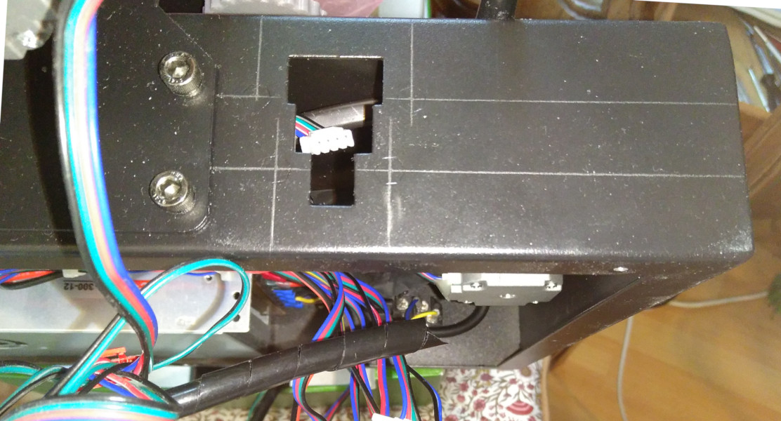
To start, first unscrew/remove everything which is attached or mounted on the main metal casing. It is better to prevent any metal dust getting onto the circuit board and/or power supply or anything else. When done, for the large cutout, draw with a pencil horizontal and vertical lines on the metal casing, using the position of the press-in nut, which is visible from the outside, like shown on the picture below:
Then place the printed drawing with some double sided sticky tape on the metal casing, using the drawn lines as guides:
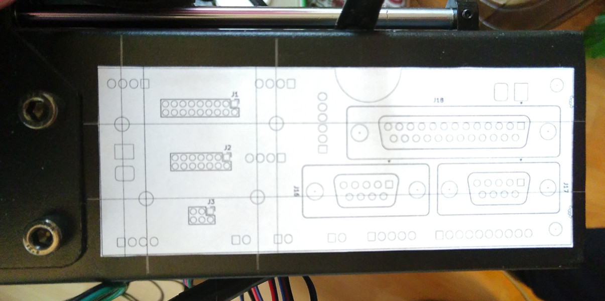
Using the printed drawing, do the following:
- Use a punch tool to mark the centre of the two holes (here visible on the right) for mounting the pcb. These need to be drilled to 3.0 mm.
- Use a sharp knife to draw lines, which mark the shape of the metal cut-out as can be seen below.
First drill the two 3.0 mm holes and counter-sink them. Then drill with a larger diameter several holes to roughly cut out the major part of the metal. Finally use a file to complete the cutout. The result should look like this:

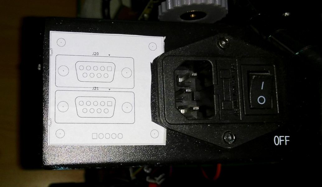
For the other side of the metal casing, the positioning is much easier, since we do not need to take into account any existing mounting points. Therefore place the drawing from above roughly as shown in the image below:
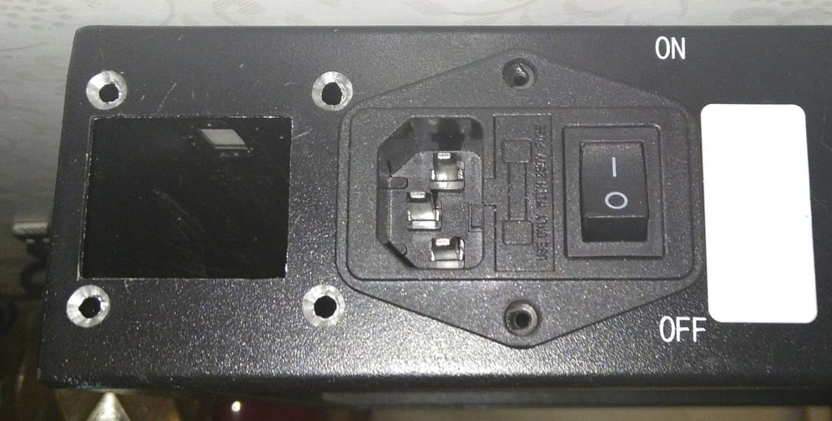
First drill the 4 holes on each side and counter-sink them. Continue with cutting with a sharp knife some lines of the cutout in the metal casing. Then use a drill to cut out the majority of the metal and use a file to finish the rectangular shape.
The result should look like the following:
Mounting circuit boards
Mount the large circuit board using the following spacers:
- 4x 2.5mm for additional distance at the 4 existing press-in nuts.
- 2x 6.0mm for the 2 mounting points at the right.
With some heat shrink and glue the 2.5mm spacers can be added more permanently to the existing press-in nuts, preventing them from falling off when trying to mount the circuit board.
The small circuit board needs 4x 6.0mm spacers for mounting.
From the inside the circuit boards should look like the following:
| Main HUB | X-stepper/Z-stepper-L |
|---|---|
 |  |
Wiring the new circuit boards - internally
Internally the following cables need to be made:
- todo.
Wiring the new circuit boards - externally
The following parts have been acquired. Supplier was Farnell (Develektro)
| Position | Part | Manufacturer | Manufacturer code | Farnell | Description |
|---|---|---|---|---|---|
| 1 | D-sub Connector Backshell | MH CONNECTORS LTD. | MHDVSL9-K | 2532964 | DMHDVSL Series Zinc Angled |
| 2 | D-sub Connector Backshell | MH CONNECTORS LTD. | MHDVSL25-K | 2532963 | DMHDVSL Series Zinc Angled |
projects/3dprinting/anycubic_i3_mega/redesign_hub_pcb.1604879893.txt.gz · Last modified: 2020/11/09 00:58 by admin
Page Tools
Except where otherwise noted, content on this wiki is licensed under the following license: CC Attribution-Noncommercial-Share Alike 4.0 International
