This is an old revision of the document!
Table of Contents
Anycubic I3 Mega Hub PCB
This page describes the process of redesigning the Anycubic I3 Mega Hub printed circuit board. The main reason is for the redesign is that it simplifies the exterior wiring substantially and helps to implement upgrades like an automatic leveller, cable chains or exchanging the original extrusion head for another head.
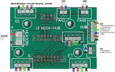
This project started in November 2019, beginning with analyzing the original I3 Mega Hub circuit board using a flatbed scanner:
| Original Anycubic I3 MEGA distribution circuit board | |
|---|---|
 |  |
| anycubic_distribution_pcb.pdf | anycubic_distribution_pcb_annotated.pdf |
The meaning of the annotations on the circuit board are:
| Label | Description |
|---|---|
| X | stepper for X-axis |
| Y | stepper for Y-axis |
| Z | stepper for Z-axis (right) |
| E0 | stepper for filament |
| E1 | stepper for Z-axis (left) |
| HEATER0 | power for the extrusion head heater |
| FAN0 | fan at the extrusion head for print cooling |
| FAN2 | fan at the extrusion head hotend cooling |
| D42 | Z-endswitch (left) |
| HUB | Connections for thermistor and Z-endswitch (right), filament- and X-endswitch |
With KiCad schematics were drawn. (Please note that from the connector marked as HUB, pin 3 (green wire) has no function and is used later on for the BLTouch automatic leveler.)
Redesign of the Mega Hub PCB
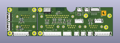
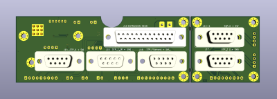
Within a period of one year, the circuit board evolved into the current design1) which has the following features:
- ESD-protection on all pins which are connected to the controller.
- Exchanging the double row JST-PHB 2.0mm Connector for D-sub connectors.
- Providing a break-off circuit board to get a connection on the other side of the housing, preventing the stepper motor wiring and metal beam under the housing.
The ESD-protection is an absolute necessary requirement for everyone who is experimenting with changing external hardware. Without protection, the risk of ESD damage is high due to the fact that for example the original temperature input from the heatbed is wired unprotected to the controller.2)
The new circuit board fits at the original location. The breaking-off circuit board (using so-called mouse-bites) is meant to be located at the other side of the printer and provides connections for the X-stepper, Z-stepper-Left and accordingly endswitches.
The reason that the original external dual row 2mm connectors were abandoned is that these are neither very robust, nor do they offer much flexibility in regard to upgrades/changes.
The schematic diagram and pinout of the board can be downloaded from here:
The housing needs to be slightly modified for the D-sub connectors. For details, see this page.
Wiring the new circuit boards - internally
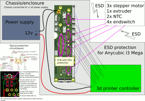
To understand how the wiring needs to be modified, please look at the following diagram. It shows how the protection works in principle:
The most important connection point for ground is realized using a REDCUBE PRESS-FIT T-Block, which has M4 thread and can be used to establish a connection with very low impedance. No (-) or ground wire shall be routed directly between the power supply and the controller circuit board. Instead, all these wires need first to go the T-Block and from there to the controller.
Internally the following cables need to be made:
- todo.
Wiring the new circuit boards - externally
The following parts have been acquired. Supplier was Farnell:
| Position | Part | Manufacturer | Manufacturer code | Farnell | Description |
|---|---|---|---|---|---|
| 1 | D-sub Connector Backshell | MH CONNECTORS LTD. | MHDVSL9-K | 2532964 | DMHDVSL Series Zinc Angled |
| 2 | D-sub Connector Backshell | MH CONNECTORS LTD. | MHDVSL25-K | 2532963 | DMHDVSL Series Zinc Angled |


